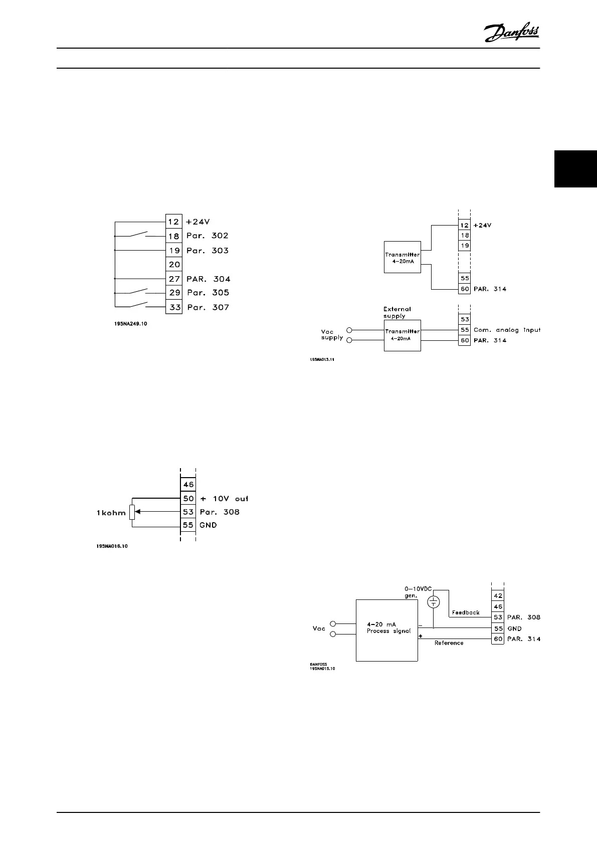
3.5.3 Speed Up/Down
Speed up/down using terminals 29/33.
•
Parameter 302 Digital input=[7] Start
•
Parameter 303 Digital input=[14] Freeze reference
•
Parameter 305 Digital input=[16] Speed up
•
Parameter 307 Digital input=[17] Speed down
Illustration 3.39 Speed Up/down Connection
3.5.4 Potentiometer Reference
Voltage reference via a potentiometer.
•
Parameter 308 Analog input=Reference [1]
•
Parameter 309 Terminal 53, min. scaling=0 V
•
Parameter 310 Terminal 53, max. scaling=10 V
Illustration 3.40 Potentiometer Reference
3.5.5 Connection of a 2-Wire Transmitter
Connection of a 2-wire transmitter as feedback to terminal
60.
•
Parameter 314 Analog input=Feedback [2]
•
Parameter 315 Terminal 60, min. scaling=4 mA
•
Parameter 316 Terminal 60, max. scaling=20 mA
Illustration 3.41 Connection of a 2-Wire Transmitter
3.5.6
4-20 mA Reference
4-20 mA reference on terminal 60 and speed feedback
signal on terminal 53.
•
Parameter 100 Configuration=[1] Speed closed loop
•
Parameter 308 Analog input=[2] Feedback
•
Parameter 309 Terminal 53, min. scaling=0 V
•
Parameter 310 Terminal 53, max. scaling=10 V
•
Parameter 314 Analog input=[1] Reference
•
Parameter 309 Terminal 60, min. scaling=4 mA
•
Parameter 310 Teminal 60, max. scaling=20 mA
Illustration 3.42 4-20 mA Reference Connection
Installation Design Guide
MG27E402 Danfoss A/S © Rev. May/2014 All rights reserved. 57
3 3
 Loading...


