3.5.7 50 Hz Counter-clockwise to 50 Hz
Clockwise
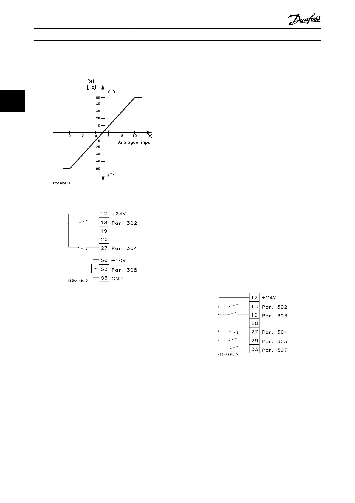
Illustration 3.43 50 Hz Counter-Clockwise to 50 Hz Clockwise
Illustration 3.44 Terminal Connection
•
Parameter 100 Configuration=[0] Speed regulation
open loop
•
Parameter 200 Output frequency range=[1] Both
directions, 0-132 Hz
•
Parameter 203 Reference range=[0] Min. ref. - Max.
ref.
•
Parameter 204 Min. reference=- 50 Hz
•
Parameter 205 Max. reference=50 Hz
•
Parameter 302 Digital input=[7] Start
•
Parameter 304 Digital input=[2] Coasting stop
inverted
•
Parameter 308 Analogue input=[1] Reference
•
Parameter 309 Terminal 53, min. scaling=0 V
•
Parameter 310 Terminal 53, max. scaling=10 V
3.5.8
Preset References
Switch between 8 preset references via 2 digital inputs and
set-up 1 and set-up 2.
•
Parameter 004 Active Setup=[5] Multisetup 1
•
Parameter 204 Min. reference=0 Hz
•
Parameter 205 Max. reference=50 Hz
•
Parameter 302 Digital input=[7] Start
•
Parameter 303 Digital input=Choice of Setup, lsb
[31]
•
Parameter 304 Digital input=[2] Coasting stop
inverted
•
Parameter 305 Digital input=Preset ref., lsb [22]
•
Parameter 307 Digital input=Preset ref., msb [23]
Set-up 1 contains the following preset references:
•
Parameter 215 Preset reference 1=5.00%
•
Parameter 216 Preset reference 2=10.00%
•
Parameter 217 Preset reference 3=25.00%
•
Parameter 218 Preset reference 4=35.00%
Set-up 2 contains the following preset references:
•
Parameter 215 Preset reference 1=40.00%
•
Parameter 216 Preset reference 2=50.00%
•
Parameter 217 Preset reference 3=70.00%
•
Parameter 218 Preset reference 4=100.00%
Illustration 3.45 Preset Reference Connection
Table 3.9 shows the output frequency for different
combinations of preset references.
Installation
Design Guide
58 Danfoss A/S © Rev. May/2014 All rights reserved. MG27E402
33
 Loading...


