P
motor
Rated motor size for VLT type
R
min
Minimum permissible brake resistor
R
rec
Recommended brake resistor (Danfoss)
P
b, cont.
Continuous braking power
Therm. relay Brake current setting of thermal relay
Ordering no. Ordering numbers for Danfoss brake resistors
Cable cross-section
Recommended minimum value based upon PVC insulated copper cable, 30 °C ambient temperature
with normal heat dissipation
Table 1.10 Definition of Variables
1.12 LCP Operation
1.12.1 Control Unit
On the front of the frequency converter there is a control
panel.
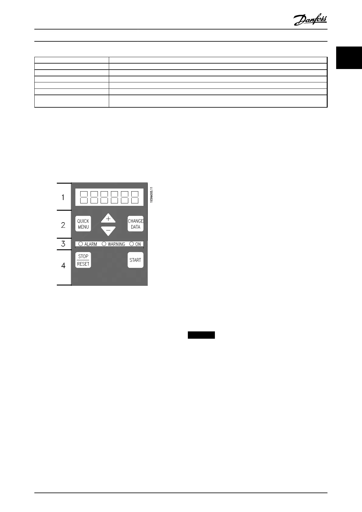
Illustration 1.13 Control Panel
The control panel is divided into 4 function groups:
1. 6-digit LED display.
2. Keys for changing parameters and shifting display
function.
3. Indicator lights.
4. Keys for local operation.
All displays of data are in the form of a 6-digit LED display
capable of showing one item of operating data contin-
uously during normal operation. As a supplement to the
display, there are 3 indicator lights for indication of mains
connection (On), warning (Warning) and alarm (Alarm).
Most of the frequency converter's parameter set-ups can
be changed immediately via the control panel, unless this
function has been programmed as [1] Locked via parameter
018 Lock for data changes.
1.12.2
Control Keys
[Quick Menu]
[Quick Menu] allows access to the parameters used for the
Quick Menu.
The [Quick Menu] key is also used if a change to a
parameter value is not to be implemented.
See also [Quick menu] + [+].
[Change Data]
[Change Data] is used for changing a setting.
The [Change Data] key is also used for confirming a
change of parameter settings.
[+]/[-]
[+]/[-] are used for selecting parameters and for changing
parameter values.
These keys are also used in Display mode for selecting the
display of an operating value.
[Quick Menu] and [+]
The [Quick Menu] + [+] keys must be pressed at the same
time to give access to all parameters. See Menu mode.
[Stop/Reset]
[Stop/Reset] is used for stopping the connected motor or
for resetting the frequency converter after a trip.
Can be selected as [1] Active or [0] Not active via parameter
014 Local stop/reset. In Display mode, the display flashes if
the stop function is activated
NOTICE
If the [Stop/Reset] key is set at [0] Not active in
parameter 014 Local stop/reset, and there is no stop
command via the digital inputs or serial communication,
the motor can only be stopped by disconnecting the
mains voltage to the frequency converter.
[Start]
[Start] is used for starting the frequency converter. It is
always active, but the [START] key cannot override a stop
command.
Introduction to VLT 2800 Design Guide
MG27E402 Danfoss A/S © Rev. May/2014 All rights reserved. 23
1
1
 Loading...


