8 Warnings and Alarms
LEDs on the front of the adjustable frequency drive
indicate if a warning or an alarm has occurred. For each
warning and alarm, there is a specic code which is shown
on the display.
A warning remains active until its cause is no longer
present. Under certain circumstances, operation of the
motor may still continue. Warning messages may in some
cases be critical.
If an alarm occurs, the adjustable frequency drive trips. To
restart operation, reset alarms once their causes have been
rectied.
Reset can be done in four ways:
•
Pressing [Reset] on the LCP.
•
Via a digital input with the Reset function.
•
Via serial communication/optional serial
communication bus.
•
By resetting automatically using the Auto Reset
function (default).
NOTICE!
After a manual reset pressing [Reset], press [Auto On] or
[Hand On] to restart the motor.
If an alarm cannot be reset, the reason may be that its
cause has not been rectied, or the alarm is trip-locked
(see also Table 8.1).
CAUTION
Alarms that are trip-locked oer extra protection,
meaning that the line power supply must be switched
o before the alarm can be reset. After being switched
back on, the adjustable frequency drive is no longer
blocked and may be reset as described previously once
the cause has been rectied.
Alarms that are not trip-locked can also be reset using
the automatic reset function in parameter 14-20 Reset
Mode (Warning: Automatic wake-up is possible!)
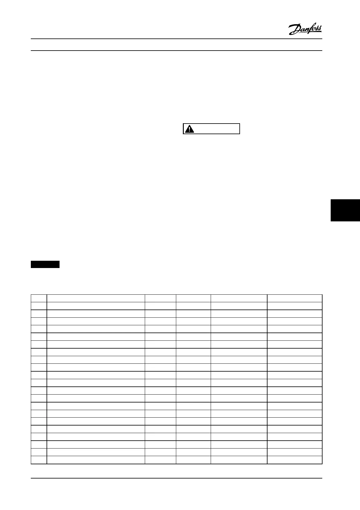
Table 8.1 species whether a warning occurs before an
alarm, or whether to display a warning or an alarm for a
given fault.
This is possible, for instance, in parameter 1-90 Motor
Thermal Protection. After an alarm or trip, the motor
carries on coasting, and the alarm and warning ash on
the adjustable frequency drive. Once the problem has
been rectied, only the alarm continues ashing.
No. Description Warning Alarm/trip Alarm/trip lock Parameter reference
1 10 volts low X
2 Live zero error (X) (X) 6-01
3 No motor (X) 1-80
4 Mains phase loss (X) (X) (X) 14-12
5 DC link voltage high X
6 DC link voltage low X
7 DC overvoltage X X
8 DC undervoltage X X
9 Inverter overloaded X X
10 Motor ETR overtemperature (X) (X) 1-90
11 Motor thermistor overtemperature (X) (X) 1-90
12 Torque limit X X
13 Overcurrent X X X
14 Ground fault X X X
15 Hardware mismatch X X
16 Short circuit X X
17 Control word timeout (X) (X) 8-04
23 Internal fan fault X
24 External fan fault X 14-53
25 Brake resistor short-circuited X
26 Brake resistor power limit (X) (X) 2-13
Warnings and Alarms Instruction Manual
MG11F522 Danfoss A/S © 08/2014 All rights reserved. 123
8 8
 Loading...


