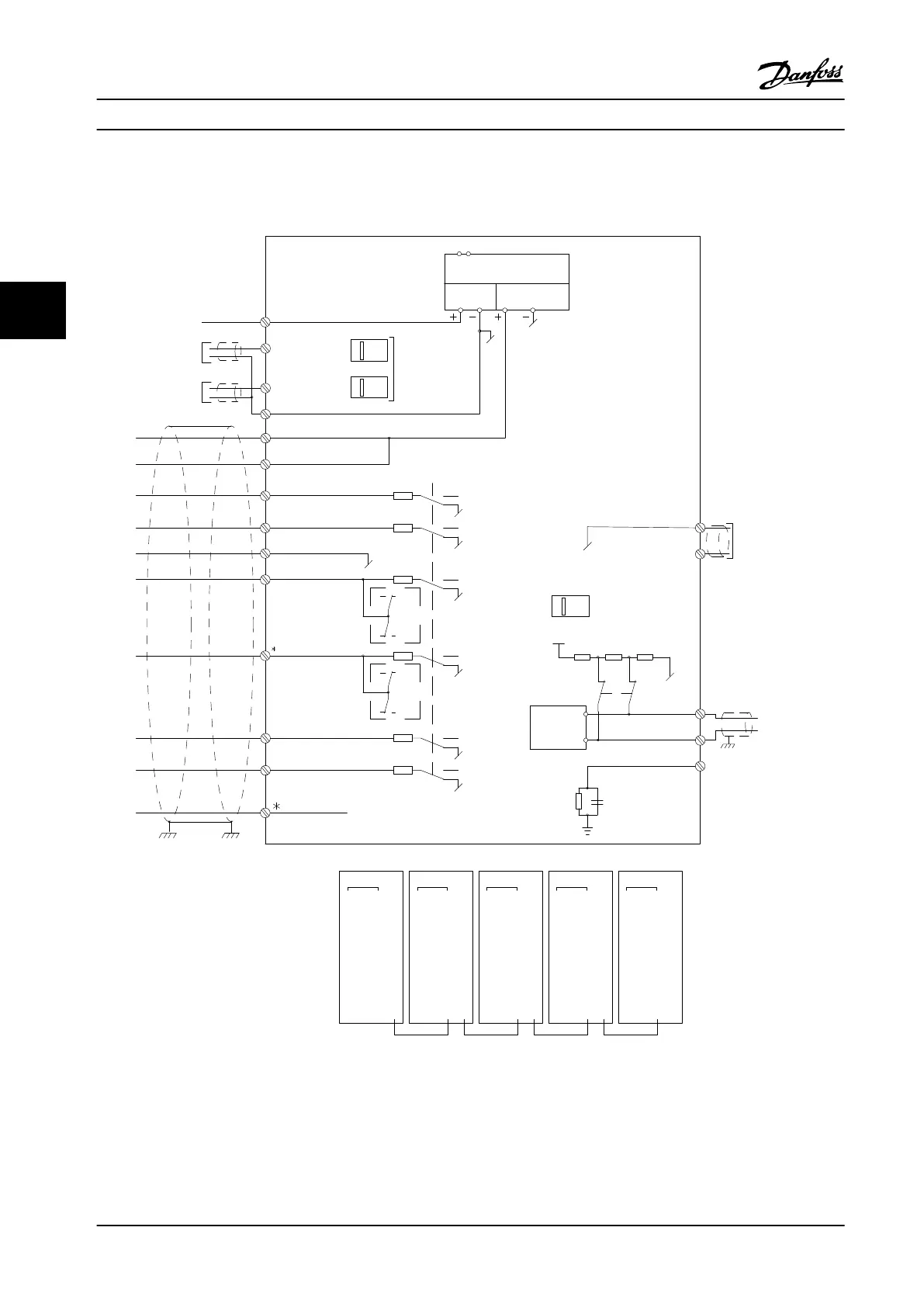
4.1.20 Electrical Installation, Control Cables
Switch Mode
Power Supply
10Vdc
15mA
24Vdc
130/200mA
Analog Output
0/4-20 mA
50 (+10 V OUT)
S201
S202
ON/I=0-20mA
OFF/U=0-10V
+10 Vdc
-10 Vdc
+10 Vdc
0/4-20 mA
-10 Vdc
+10 Vdc
0/4-20 mA
53 (A IN)
54 (A IN )
55 (COM A IN )
(COM A OUT) 39
(A OUT) 42
12 (+24V OUT )
13 (+24V OUT )
18 (D IN)
19 (D IN )
20 (COM D IN)
27 (D IN/OUT )
24 V
24 V
OV
OV
29 (D IN/OUT )
32 (D IN )
33 (D IN )
37 (D IN )
5 6 7 8 5 6 7 8
11
CI45
MODULE
CI45
MODULE
CI45
MODULE
CI45
MODULE
CI45
MODULE
12 13 14 11 12 13 14 11 12 13 14 11 12 13 14 11 12 13 14
15 16 17 1815 16 17 1815 16 17 1815 16 17 1815 16 17 18
5 6 7 8 5 6 7 8 5 6 7 8
1 12 23 34 4 1 2 3 4 1 2 3 4 1 2 3 4
P 5-00
24V (NPN)
0V (PNP)
24V (NPN)
0V (PNP)
24V (NPN)
0V (PNP)
24V (NPN)
0V (PNP)
24V (NPN)
0V (PNP)
24V (NPN)
0V (PNP)
ON=Terminated
OFF=Open
(PNP) = Source
(NPN) = Sink
RS-485
(COM RS-485) 61
(P RS-485) 68
(N RS-485) 69
RS - 485
Interface
S801
S801
5V
ON
ON
ON
1
1
1
2
2
2
CONTROL CARD CONNCECTION
130BB759.10
Figure 4.21 Electrical Terminals Diagram
A=Analog, D=Digital
*Terminal 37 (optional) is used for STO. For STO installation instructions, refer to the Safe Torque O Instruction Manual for
Danfoss VLT
®
Adjustable Frequency Drives.
**Do not connect cable shield.
Electrical Installation
VLT
®
HVAC Drive FC 102
58 Danfoss A/S © 08/2014 All rights reserved. MG11F522
44
 Loading...


