Enclosure
sizes
Terminal Torque [Nm] (in-lbs) Bolt size
F Line power
Motor
19–40
(168–354)
M10
Load sharing 19–40
(168-354)
M10
Brake
Regen
8.5-20.5
(75-181)
8.5-20.5
(75-181)
M8
M8
Table 4.3 Torque for Terminals
4.1.6
Shielded Cables
WARNING
Danfoss recommends using shielded cables between the
LCL lter and the adjustable frequency drive. Non-
shielded cables can be used between the transformer
and the LCL lter input side.
Make sure to connect shielded and armored cables
properly to ensure high EMC immunity and low emissions.
The connection can be made using either cable
connectors or clamps.
•
EMC cable connectors: Available cable connectors
can be used to ensure optimum EMC connection.
•
EMC cable clamp: Clamps allowing for easy
connection are supplied with the adjustable
frequency drive.
4.1.7
Motor Cable
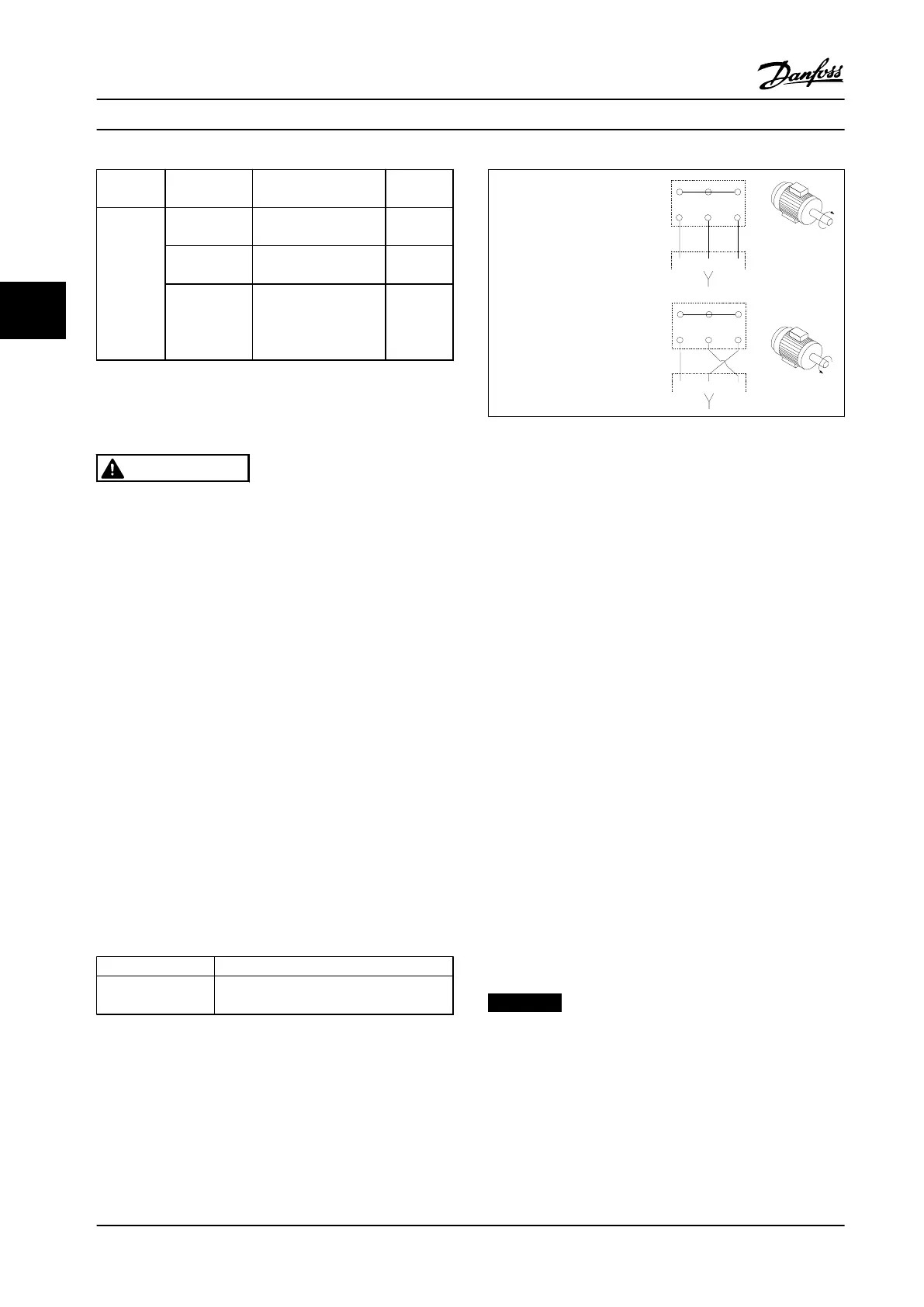
Connect the motor to terminals U/T1/96, V/T2/97, W/T3/98.
Ground to terminal 99. All types of 3-phase asynchronous
standard motors can be used with an adjustable frequency
drive. The factory setting is clockwise rotation with the
adjustable frequency drive output connected as follows:
Terminal number Function
96, 97, 98
99
Line power U/T1, V/T2, W/T3
Ground
Table 4.4 Line Power Terminals
•
Terminal U/T1/96 connected
to U-phase
•
Terminal V/T2/97 connected
to V-phase
•
Terminal W/T3/98 connected
to W-phase
175HA036.11
U
1
V
1
W
1
96 97 98
FC
Motor
U
2
V
2
W
2
U
1
V
1
W
1
96 97 98
FC
Motor
U
2
V
2
W
2
Table 4.5 Wiring for Motor Directions
The direction of rotation can be changed by switching two phases in
the motor cable or by changing the setting of parameter 4-10 Motor
Speed Direction.
To perform motor rotation check, follow the steps in
parameter 1-28 Motor Rotation Check.
F enclosure requirements
F1/F3 requirements
Attach an equal number of wires to both inverter module
terminals. To obtain an equal number, motor phase cable
quantities must be multiples of 2, resulting in 2, 4, 6, or 8
(1 cable is not allowed). The cables are required to be of
equal length within 10% between the inverter module
terminals and the rst common point of a phase. The
recommended common point is the motor terminals.
F2/F4 requirements: Attach an equal number of wires to
both inverter module terminals. To obtain an equal
number, motor phase cable quantities must be multiples of
3, resulting in 3, 6, 9, or 12 (1 or 2 cables are not allowed).
The wires are required to be of equal length within 10%
between the inverter module terminals and the rst
common point of a phase. The recommended common
point is the motor terminals.
Output junction box requirements
The length, a minimum of 2.5 m (8 ft), and quantity of
cables must be equal from each inverter module to the
common terminal in the junction box.
NOTICE!
If a retrot application requires an unequal number of
wires per phase, consult the factory for requirements
and documentation, or use the top/bottom entry side
enclosure option.
Electrical Installation
VLT
®
HVAC Drive FC 102
48 Danfoss A/S © 08/2014 All rights reserved. MG11F522
44
 Loading...


