4 Electrical Installation
4.1 Electrical Installation
4.1.1 Power Connections
Cabling and fusing
NOTICE!
Cables in General
All cabling must comply with national and local
regulations on cable cross-sections and ambient
temperature. UL applications require 75 °C (167 °F)
copper conductors. 75 °C (167 °F) and 90 °C (194 °F)
copper conductors are thermally acceptable for the
adjustable frequency drive to use in non-UL applications.
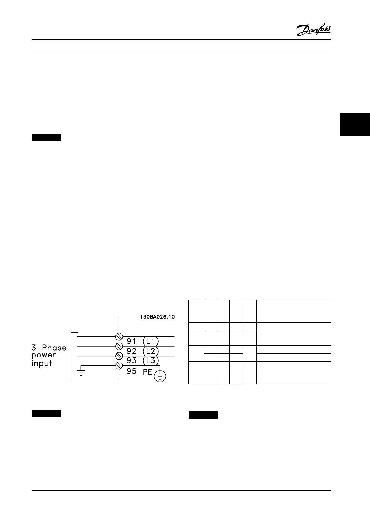
The power cable connections are located as shown in
Figure 4.1. Dimensioning of cable cross-section must be
done in accordance with the current ratings and local
legislation. See chapter 7 General
Specications for details.
If the adjustable frequency drive does not have built-in
fuses, use the recommended fuses to protect it. See
chapter 4.1.15 Fuse
Specications for recommended fuses.
Always ensure that proper fusing is done according to
local regulations.
The AC line input connection is tted to the line power
switch if this switch is included.
Figure 4.1 Power Cable Connections
NOTICE!
The motor cable must be shielded/armored. If a non-
shielded/unarmored cable is used, some EMC
requirements are not complied with. To comply with EMC
emission specications, use a shielded/armored motor
cable. For more information, see EMC specications in the
product-related design guide.
See chapter 7 General Specications for correct
dimensioning of motor cable cross-section and length.
Shielding of cables
Avoid installation with twisted shield ends (pigtails). They
spoil the shielding eect at higher frequencies. If it is
necessary to break the shield to install a motor isolator or
motor contactor, continue the shield at the lowest possible
HF impedance.
Connect the motor cable shield to both the decoupling
plate on the adjustable frequency drive and to the metal
housing on the motor.
Make the shield connections with the largest possible
surface area (cable clamp). These connections are made by
using the supplied installation devices within the
adjustable frequency drive.
Cable length and cross-section
The adjustable frequency drive has been EMC-tested with a
given cable length. Keep the motor cable as short as
possible to reduce the noise level and leakage currents.
Switching frequency
When adjustable frequency drives are used together with
sine-wave lters to reduce the acoustic noise from a motor,
set the switching frequency according to
parameter 14-01 Switching Frequency.
Term.
numb
er
96 97 98 99
U V W
PE
1)
Motor voltage 0–100% of AC line
voltage.
3 wires out of motor.
U1 V1 W1
PE
1)
Delta-connected.
W2 U2 V2 6 wires out of motor.
U1 V1 W1
PE
1)
Star-connected U2, V2, W2
U2, V2 and W2 to be intercon-
nected separately.
Table 4.1 Motor Terminals
1) Protected Ground Connection
NOTICE!
In motors without phase insulation paper or other
insulation reinforcement suitable for operation with
voltage supply (such as a adjustable frequency drive), t
a sine-wave lter on the adjustable frequency drive
output.
Electrical Installation Instruction Manual
MG11F522 Danfoss A/S © 08/2014 All rights reserved. 39
4 4
 Loading...


