Terminal locations - options cabinet with circuit breaker/molded case switch (F3 and F4)
0.0 [0.00]
134.6 [5.30]
104.3 [4.11]
0.0 [0.00]
179.3 [7.06]
219.6 [8.65]
294.6 [11.60]
334.8 [13.18]
409.8 [16.14]
436.9 [17.20]
0.0 [0.00]
532.9 [20.98]
0.0 [0.00]
44.4 [1.75]
244.4 [9.62]
154.0 [6.06]
344.0 [13.54]
1
2
3
4
5
130BA852.11
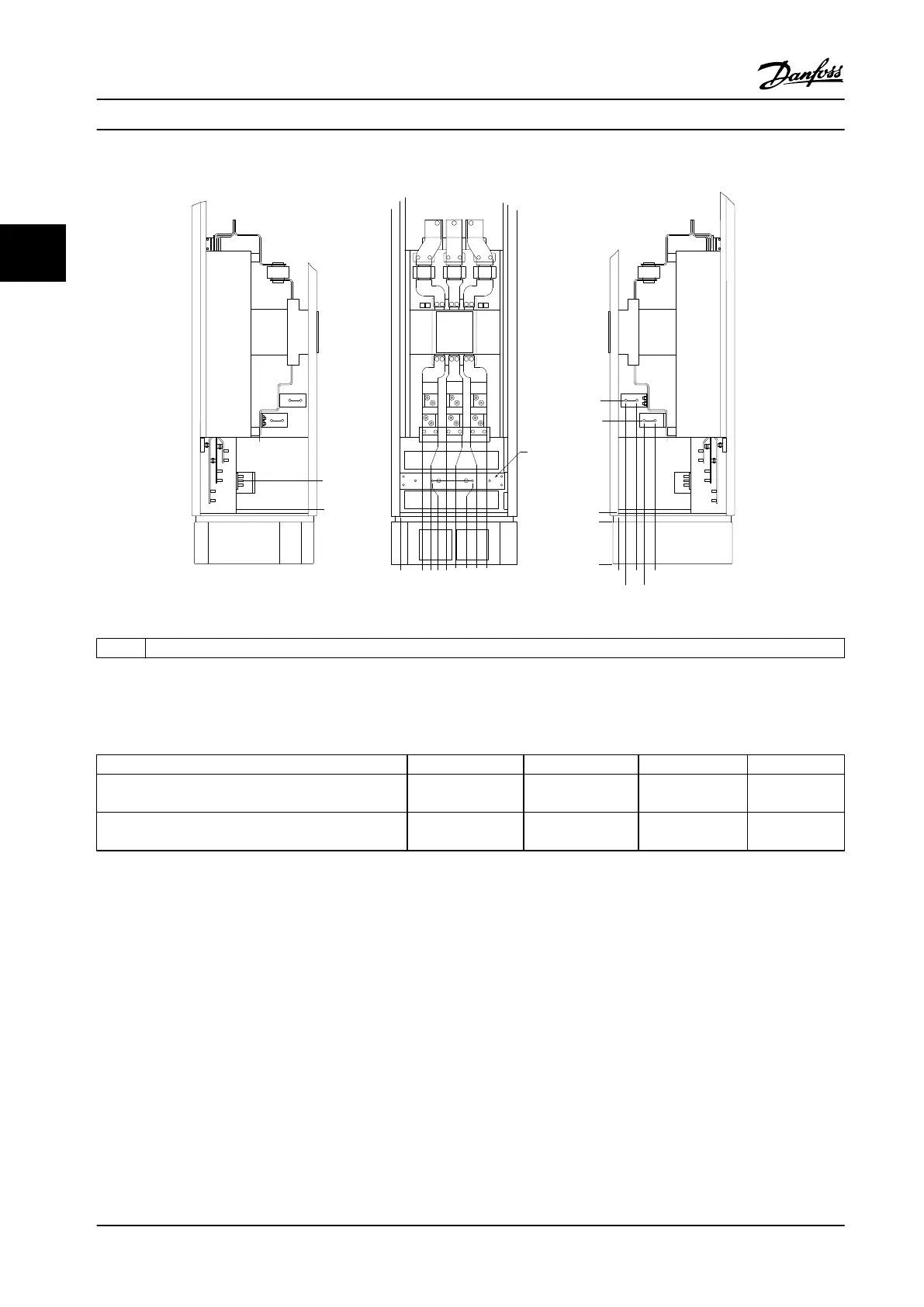
1 Ground bar
Figure 3.30 Terminal Locations - Options Cabinet with Circuit Breaker/Molded Case Switch (Left Side, Front and Right Side View). The
Connector Plate is 42 mm (1.65 in) below .0 level.
Power size 2 3 4 5
500 kW (650 hp) (480 V), 710–800 kW (950–1075 hp)
(690 V)
34.9 86.9 122.2 174.2
560–1000 kW (750–1350 hp) (480 V), 900–1400 kW
(1200–1875 hp) (690 V)
46.3 98.3 119.0 171.0
Table 3.7 Dimensions for Terminal
3.3.5
Cooling and Airow
Cooling
Cooling can be obtained in dierent ways:
•
By using the cooling ducts at the bottom and top
of the unit.
•
By adding and removing air from the back of the
unit.
•
By combining the cooling possibilities.
Duct cooling
A dedicated option has been developed to optimize instal-
lation of IP00/chassis adjustable frequency drives in Rittal
TS8 enclosures. The option uses the fan of the adjustable
frequency drive for forced air cooling of the backchannel.
Air that escapes from the top of enclosure could be ducted
outside a facility. Then heat losses from the backchannel
are not dissipated within the control room, reducing air-
conditioning requirements of the facility.
See chapter 3.4.1 Installation of Duct Cooling Kit in Rittal
Enclosures, for further information.
Back cooling
The backchannel air can also be vented in and out the
back of a Rittal TS8 enclosure. Such back cooling oers a
solution where the backchannel could take air from
outside the facility and return the heat losses outside the
facility, thus reducing air-conditioning requirements.
Mechanical Installation
VLT
®
HVAC Drive FC 102
28 Danfoss A/S © 08/2014 All rights reserved. MG11F522
33
 Loading...


