6.1.4 5-1* Digital Inputs
Parameters for conguring the input functions for the
input terminals.
The digital inputs are used for selecting various functions
in the adjustable frequency drive. All digital inputs can be
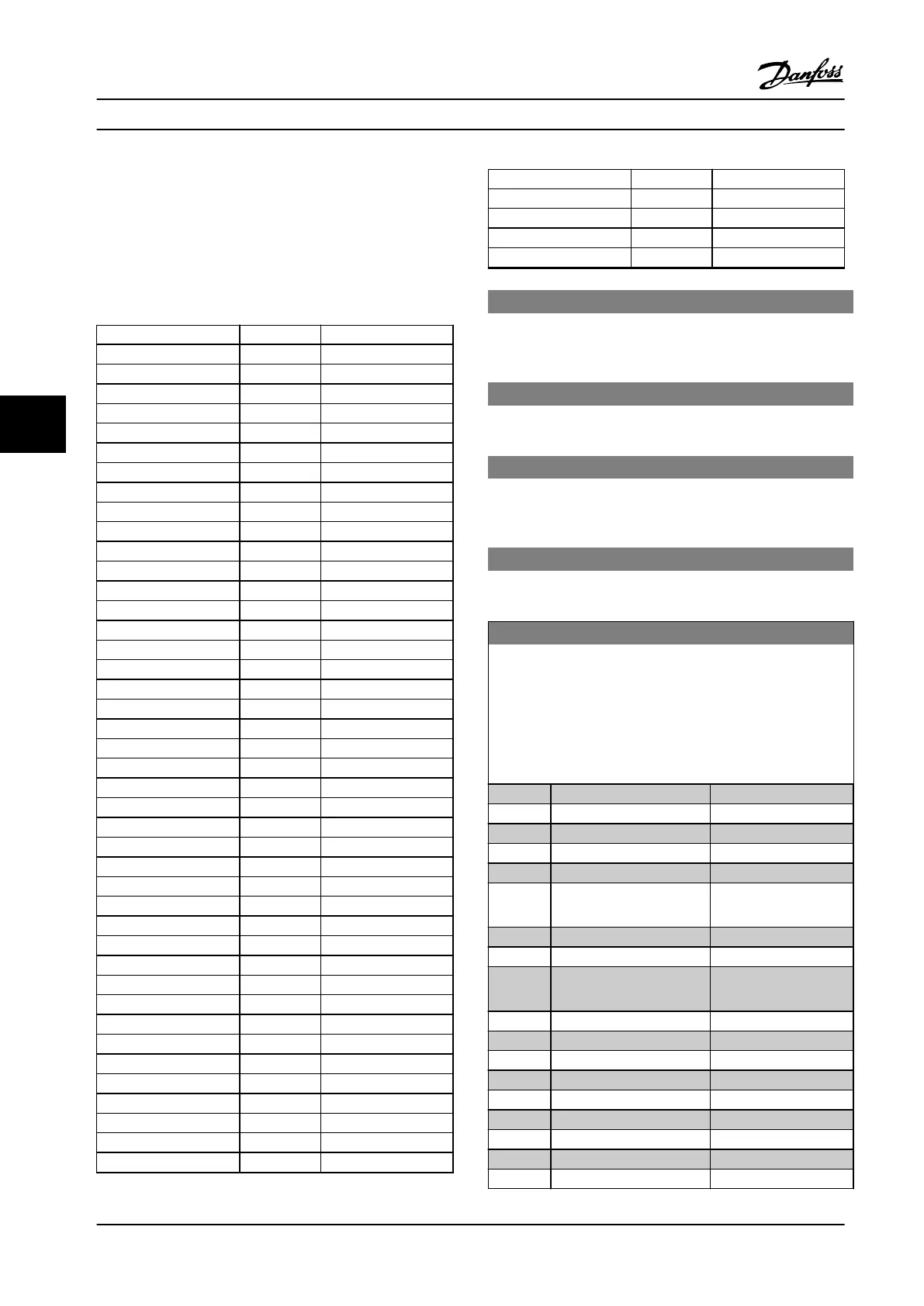
set to the following functions:
Digital input function Select Terminal
No operation [0] All *terminal 19, 32, 33
Reset [1] All
Coast inverse [2] 27
Coast and reset inverse [3] All
DC brake inverse [5] All
Stop inverse [6] All
External interlock [7] All
Start [8] All *terminal 18
Latched start [9] All
Reversing [10] All
Start reversing [11] All
Jog [14] All *terminal 29
Preset reference on [15] All
Preset ref bit 0 [16] All
Preset ref bit 1 [17] All
Preset ref bit 2 [18] All
Freeze reference [19] All
Freeze output [20] All
Speed up [21] All
Slow [22] All
Set-up select bit 0 [23] All
Set-up select bit 1 [24] All
Pulse input [32] Terminal 29, 33
Ramp bit 0 [34] All
Mains failure inverse [36] All
Fire mode [37] All
Run permissive [52] All
Hand start [53] All
Auto-start [54] All
DigiPot increase [55] All
DigiPot decrease [56] All
DigiPot clear [57] All
Counter A (up) [60] 29, 33
Counter A (down) [61] 29, 33
Reset counter A [62] All
Counter B (up) [63] 29, 33
Counter B (down) [64] 29, 33
Reset counter B [65] All
Sleep mode [66] All
Reset maintenance word [78] All
PTC card 1 [80] All
Lead pump start [120] All
Digital input function Select Terminal
Lead pump alternation [121] All
Pump 1 interlock [130] All
Pump 2 interlock [131] All
Pump 3 interlock [132] All
5-12 Terminal 27 Digital Input
The parameter contains all options and functions listed in
parameter group 5-1* Digital Inputs except for option [32] Pulse
input.
5-13 Terminal 29 Digital Input
The parameter contains all options and functions listed in
parameter group 5-1* Digital Inputs.
5-14 Terminal 32 Digital Input
The parameter contains all options and functions listed in
parameter group 5-1* Digital Inputs except for option [32] Pulse
input.
5-15 Terminal 33 Digital Input
The parameter contains all options and functions listed in
parameter group 5-1* Digital Inputs.
5-40 Function Relay
Array [8]
(Relay 1 [0], Relay 2 [1]
Option MCB 105: Relay 7 [6], Relay 8 [7] and Relay 9 [8]).
Select options to dene the function of the relays.
The selection of each mechanical relay is realized in an array
parameter.
Option: Function:
[0] No operation
[1] Control ready
[2] Drive ready
[3] Drive rdy/rem ctrl
[4] Standby / no warning
[5] Running Default setting for relay
2.
[6] Running / no warning
[8] Run on ref/no warn
[9] Alarm Default setting for relay
1.
[10] Alarm or warning
[11] At torque limit
[12] Out of current range
[13] Below current, low
[14] Above current, high
[15] Out of speed range
[16] Below speed, low
[17] Above speed, high
[18] Out of feedb. range
How to Program
VLT
®
HVAC Drive FC 102
94 Danfoss A/S © 08/2014 All rights reserved. MG11F522
66
 Loading...


