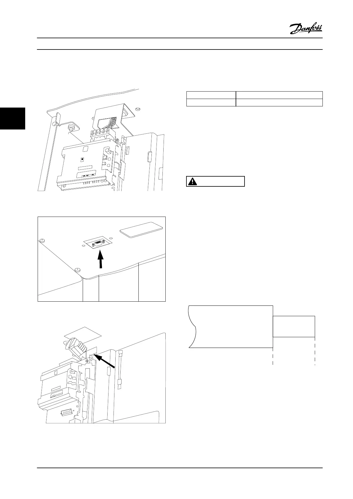
Kit number for serial communication bus top connection:
176F1742.
130BA867.10
Probus Option A
FC300 Service
Figure 4.14 Top Connection for Serial Communication Bus.
Figure 4.15 Serial Communication Bus Top Entry Kit, Installed
Figure 4.16 Shield Termination/Strain Relief for Serial
Communication Bus Conductors
Installation of 24 V DC external supply
Torque: 0.5–0.6 Nm (5 in-lbs)
Screw size: M3
Terminal number Function
35 (-), 36 (+) 24 V DC external supply
Table 4.29 Terminals for 24 V DC External Supply
24 V DC external supply can be used as low-voltage supply
to the control card and any option cards installed. This
enables full operation of the LCP (including parameter
setting) without connection to line power. Note that a
warning of low voltage is given when 24 V DC has been
connected; however, there is no tripping.
WARNING
To ensure correct galvanic isolation (type PELV) on the
control terminals of the adjustable frequency drive, use
24 V DC supply of type PELV.
4.1.18 Access to Control Terminals
All terminals to the control cables are located beneath the
LCP. They are accessed by opening the door of the IP21/
IP54 unit, or by removing the covers of the IP00 unit.
4.1.19
Electrical Installation, Control
Terminals
To connect the cable to the terminal:
1. Strip o 9–10 mm (0.34–0.39 in) of the insulation.
130BA150.10
9 - 10 mm
(0.37 in)
Figure 4.17 Strip
o Insulation
2.
Insert a screwdriver
1)
in the square hole.
3. Insert the cable in the adjacent circular hole.
Electrical Installation
VLT
®
HVAC Drive FC 102
56 Danfoss A/S © 08/2014 All rights reserved. MG11F522
44
 Loading...


