4.1.2 Grounding
To obtain electromagnetic compatibility (EMC), consider
the following during installation:
•
Safety grounding: For safety reasons, ground the
adjustable frequency drive appropriately due to
its high leakage current. Always follow local
safety regulations.
•
High-frequency grounding: Keep the ground wire
connections as short as possible.
Connect the
dierent ground systems at the lowest
possible conductor impedance. The lowest possible
conductor impedance is obtained by keeping the
conductor as short as possible and by using the greatest
possible surface area.
The metal cabinets of the dierent devices are mounted
on the cabinet rear plate using the lowest possible HF
impedance. Dierent HF voltages are then avoided for the
individual devices. Also the risk of radio interference
currents running in connection cables that may be used
between the devices is avoided. The radio interference has
been reduced.
To obtain a low HF impedance, use the fastening bolts of
the devices as HF connection to the rear plate. It is
necessary to remove insulating paint and the like from the
fastening points.
4.1.3
Extra Protection (RCD)
If local safety regulations are complied with, ELCB relays,
multiple protective grounding can be used as extra
protection.
A ground fault may cause a DC component to develop in
the fault current.
If ELCB relays are used, observe local regulations. Relays
must be suitable for the protection of 3-phase equipment
with a bridge
rectier and for a brief discharge on power-
up.
See also Special Conditions in the product relevant design
guide.
4.1.4
RFI Switch
Line power supply isolated from ground
If the adjustable frequency drive is supplied from an
isolated line power source (IT line power, oating delta and
grounded delta) or TT/TN-S line power with grounded leg,
turn o the RFI switch via parameter 14-50 RFI 1 on both
the adjustable frequency drive and the lter. For further
reference, see IEC 364-3.
Set parameter 14-50 RFI 1 to [ON]
•
If optimum EMC performance is needed.
•
Parallel motors are connected.
•
The motor cable length is above 25 m (82 ft).
In OFF, the internal RFI capacities
(lter capacitors)
between the enclosure and the intermediate circuit are cut
o to avoid damage to the intermediate circuit and to
reduce the ground capacity currents (according to IEC
61800-3).
Also refer to the Application Note VLT on IT Line Power. It is
important to use isolation monitors suited for power
electronics (IEC 61557-8).
4.1.5
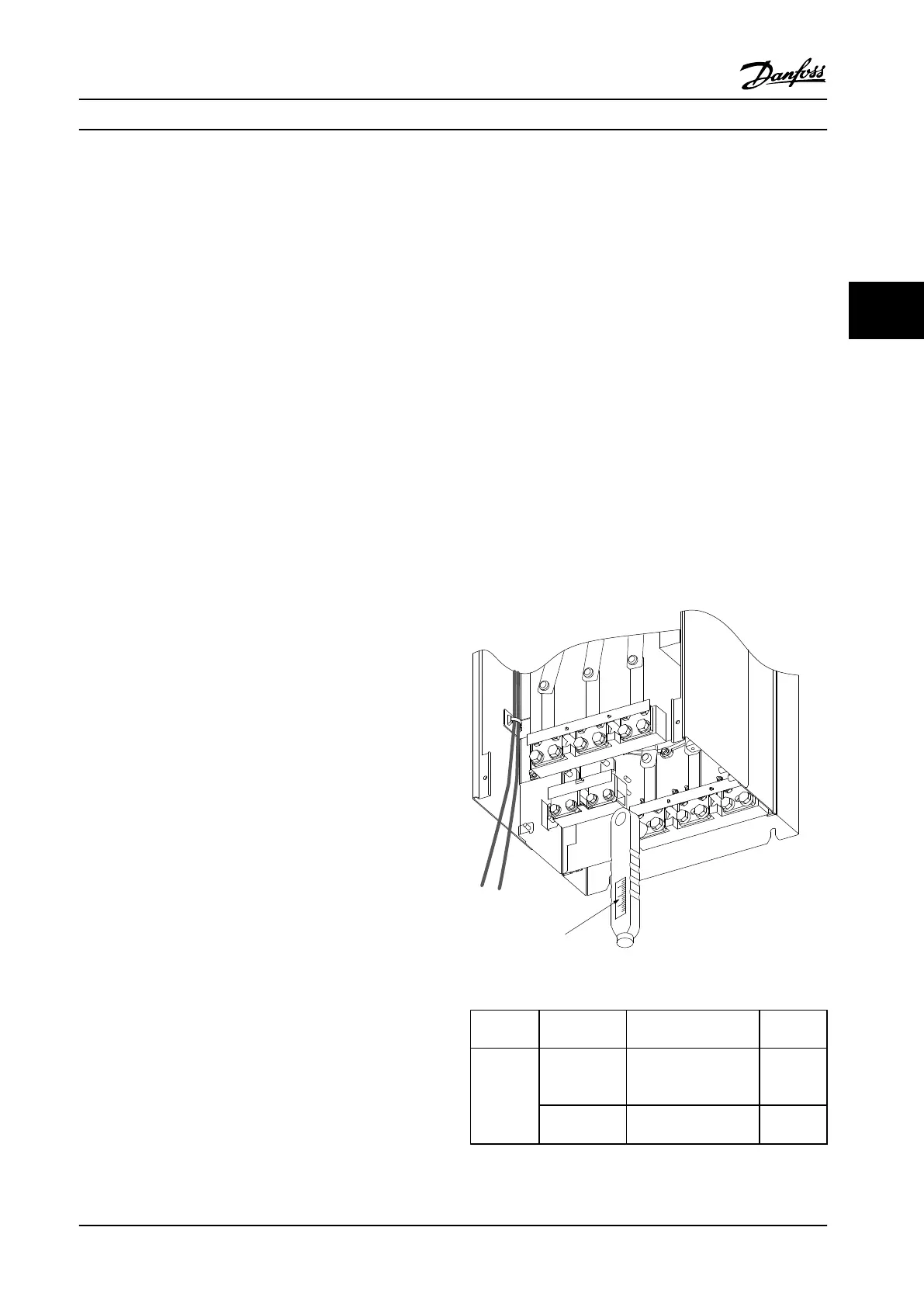
Torque
Tighten all electrical connections with the correct torque.
Too low or too high torque results in a bad electrical
connection. To ensure correct torque, use a torque wrench.
176FA247.12
Nm/in-lbs
-DC 88
+DC 89
R/L1 91
S/L2 92
T/L3 93
U/T1 96
V/T2 97
W/T3
Figure 4.10 Tighten Bolts with a Torque Wrench
Enclosure
sizes
Terminal Torque [Nm] (in-lbs) Bolt size
E Line power
Motor
Load sharing
19–40
(168–354)
M10
Brake
8.5–20.5
(75–181)
M8
Electrical Installation Instruction Manual
MG11F522 Danfoss A/S © 08/2014 All rights reserved. 47
4 4
 Loading...


