FC 300 Design Guide
How to Program
Function:
The Maximum reference is the highest value
obtained by the sum of all re f erenc es. The unit
follows the choice o f configuration in par. 1-00.
Speed control, closed loop: RPM
Torque control, speed feedback: Nm
" 3-1* References
3-10 Preset Referen ce
Array [8]
Range:
-100.00-100.00%
*
0.00%
Function:
Eight different preset references
(0-7) can be
programmed via array programming. The preset
reference is stated as a percentage of the value
Maximum Reference (par. 3
-03) or as a percentage
of the other e xternal references. If a Minimum
Reference 0 (Par. 3-02) is prog rammed, the
preset reference as a
percentage is calculated
onthebasisofthedifferencebetweenMaximum
Reference and Minimum Reference. A fterwards,
the value is ad d
ed to Minimum Reference. S ele c t
Preset ref enable on th e matching digital inputs
when using p reset referenc es.
3-12 Catch up/slow-down Value
Range:
0.00 - 100.00%
*
0.00%
Function:
Enables ente
ring a percentage value (relative)
which is either added to or deducted from the
actual referenc e. If Catch up is selected via one
of the di
gital inputs (par. 5-1 0 to par. 5-15),
the perce ntage (relative) value is added to
the total reference. If Slow down is selected
via on
e of the digital inputs (par. 5-10 to
par. 5-15),thepercentage(relative)valueis
deducted from the total reference.
3-13 Reference Site
Opt
ion:
*
Linked to Hand / Auto [0]
Remote [1]
Local [2]
Function:
Decides which resulting reference is active. If
Linked to Hand / Auto [0] is select ed, the resulting
reference depends on whether the drive is in Hand
or Auto mode. In Hand mode the local reference
is used, and in Auto mode the remote reference is
used. Select Remote [1]tousetheremotereference
in both Hand mode and Auto mode. Select Local [2]
to use the local reference in both Hand mode and
Auto mod e (par. 3-14) Prese t Relative Reference.
3-14 Prese t Relative Reference
Range:
-100.00 - 10000.00 %
*
0.00%
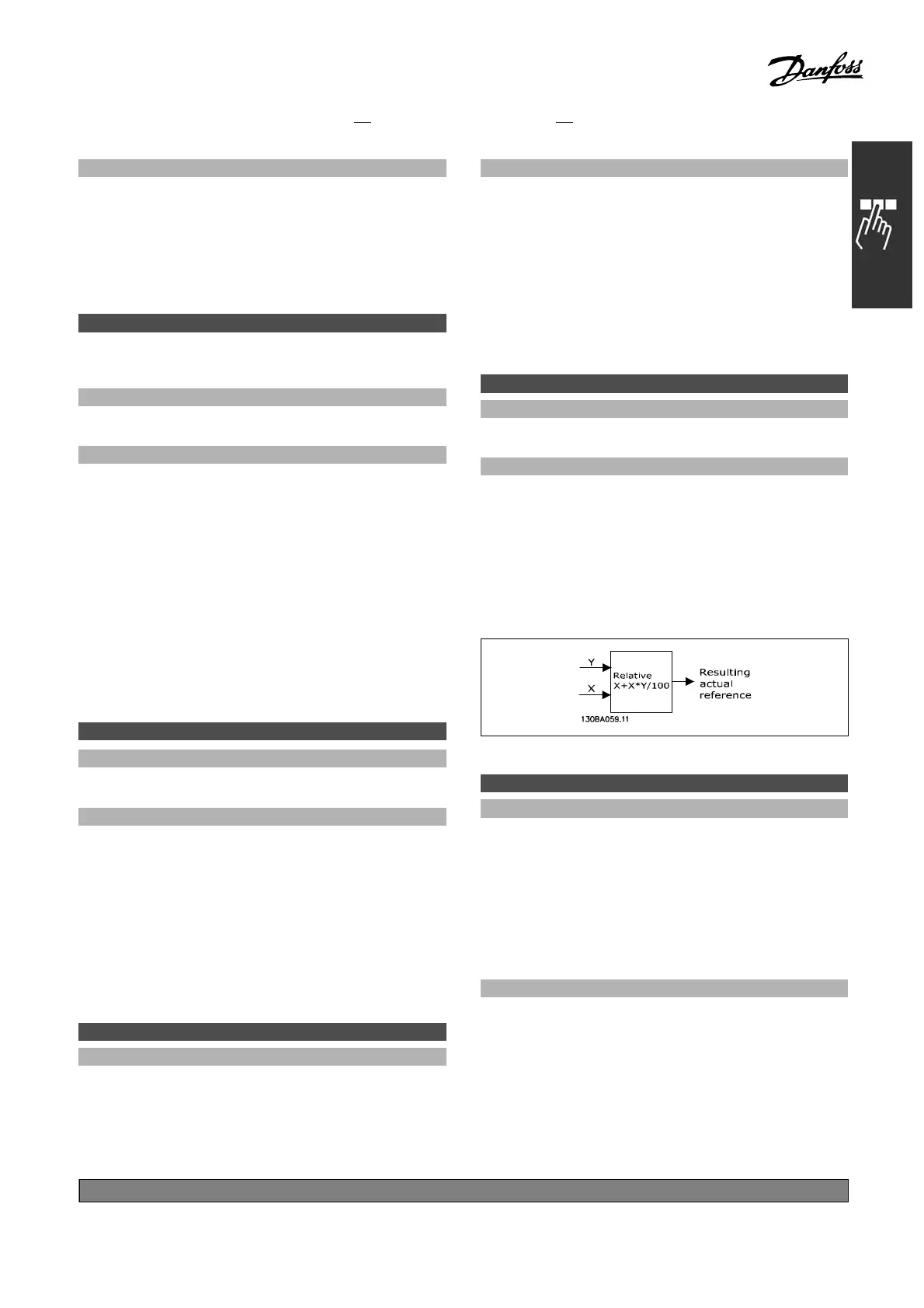
Function:
Defines a fixed value (in %) a dded to the
variable value (defined in par. 3-18 and called
Y in the illustration below). This sum (Y) is
multiplied with the actual reference (called X in
the illustration below) and the result is added
to the actual reference (X+X*Y/100).
3-15 Reference R esource 1
Option:
No function [0]
*
Analog input 53 [1]
Analog input 54 [2]
Frequency input 29 [7]
Frequency input 33 [8]
Local bus reference [11]
Digital pot.meter [20]
Function:
Adding up to three different reference signals
to compose the actual reference.
Defines w hat reference input should be treated as
thesourceofthefirstreferencesignal.
Par. 3-15 cannot be adjusted while the
motor is running.
*
default setting ()display text []value for use in communication via serial communication port
155
MG.33.B
3.22 - VLT is a registered Danfoss trademark
 Loading...


