FC 300 Design Guide
How to Program
3-16 Refere nce Resource 2
Option:
No function [0]
Analog input 53 [1]
Analog input 54 [2]
Frequency input 29 [7]
Frequency input 33 [8]
Local bus reference [11]
*
Digital pot.meter [20]
Function:
Up to three different reference signals can be
added to compose the ac tual reference.
Defines what reference input should be treated as
the source of the second reference signal.
Par. 3-16 cannot be adjusted while the
motor is running.
3-17 Refere nce Resource 3
Option:
No function [0]
Analog input 53 [1]
Analog input 54 [2]
Frequency input 29 [7]
Frequency input 33 [8]
*
Local bus reference [11]
Digital pot.meter [20]
Function:
Up to three different reference signals can be
added to compose the ac tual reference.
Defines what reference input should be treated as
the source of the third refere nce signal.
Par. 3-17 cannot be adjusted while the
motor is running.
3-18 Relative Scaling Reference Resource
Option:
*
No function [0]
Analog input 53 [1]
Analog input 54 [2]
Frequency input 29 [7]
Frequency input 33 [8]
Local bus reference [11]
Digital pot.meter [20]
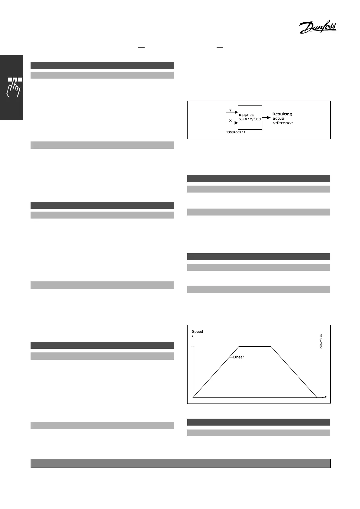
Function:
Defines that the input is treated as the source of the
relative reference. This reference (in %) is added
to the fixed value from par. 3-14. The sum (called
Y in the illustration below ) is mu ltiplied with the
actual reference (called X be low ) and the result is
added to the actual reference (X+X*Y/100).
Par. 3-18 cannot be adjusted while the
motor is running.
3-19 Jog Speed [RPM]
Range:
0-par. 4-13RPM
*
200RPM
Function:
The jog speed n
JOG
is a fixed output speed. The
adjustable frequency drive runs at this speed
when the jog function is active.
" 3-4* Ramp 1
3-40 Ramp 1 Type
Option:
*
Linear [0]
Function:
Selects the desired ramp type, depending on
requirements for acceleration/deceleration.
3-41 Ramp 1 Ramp-up Time
Range:
0.01 - 3600.00 s
*
ExpressionLimits
*
default setting ()display text []value for use in communication via serial communication port
156
MG.33.B
3.22 - VLT is a registered Danfoss trademark
 Loading...


