5-40 Function Relay
Array [9]
(Relay 1 [0], Relay 2 [1], Relay 3 [2] (MCB 113), Relay 4 [3] (MCB
113), Relay 5 [4] (MCB 113), Relay 6 [5] (MCB 113), Relay 7 [6]
(MCB 105), Relay 8 [7] (MCB 105), Relay 9 [8] (MCB 105))
Option: Function:
bus connection or [Hand on] or
[Auto on] ), and a Stop has been last
command.
[124] Running reverse Output is high when the frequency
converter is running counter
clockwise (the logical product of the
status bits ‘running’ AND ‘reverse’).
[125] Drive in hand mode Output is high when the frequency
converter is in [Hand on] mode (as
indicated by the LED light above
[Hand on]).
[126] Drive in auto mode Output is high when the frequency
converter is in ‘Auto’ mode (as
indicated by LED on above [Auto
on] ).
NOTE
Remember to set switches S201 (A53) and S202 (A54) as
specified below when performing a control card test in
14-22 Operation Mode. Otherwise, the test will fail!
14-22 Operation Mode
Option: Function:
Use this parameter to specify normal
operation; to perform tests; or to initialise all
parameters except 15-03 Power Up's,
15-04 Over Temp's and 15-05 Over Volt's. This
function is active only when the power is
cycled to the frequency converter.
Select [0] Normal operation for normal
operation of the frequency converter with the
motor in the selected application.
Select [1] Control card test to test the analog
and digital inputs and outputs and the +10 V
control voltage. The test requires a test
connector with internal connections. Use the
following procedure for the control card test:
1.
Select [1] Control card test .
2. Disconnect the mains supply and
wait for the light in the display to go
out.
3. Set switches S201 (A53) and S202
(A54) = ‘ON’ / I.
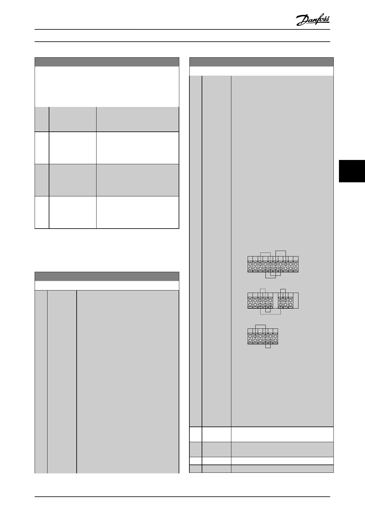
4. Insert the test plug (see below).
5. Connect to mains supply.
14-22 Operation Mode
Option: Function:
6. Carry out various tests.
7. The results are displayed on the LCP
and the frequency converter moves
into an infinite loop.
8.
14-22 Operation Mode is automat-
ically set to Normal operation. Carry
out a power cycle to start up in
Normal operation after a control
card test.
If the test is OK
LCP read-out: Control Card OK.
Disconnect the mains supply and remove the
test plug. The green LED on the Control Card
will light up.
If the test fails
LCP read-out: Control Card I/O failure.
Replace the frequency converter or Control
card. The red LED on the Control Card is
turned on. Test plugs (connect the following
terminals to each other): 18 - 27 - 32; 19 - 29
- 33; 42 - 53 - 54
130BA097.12
FC 302
FC 301
FC 301 &
FC 302
1312 18 37322719 29 33 20
5039 42 5453 55
191812 13 203327 32
Illustration 6.13
Select Initialization [2] to reset all parameter
values to default settings, except for
15-03 Power Up's, 15-04 Over Temp's, and
15-05 Over Volt's. The frequency converter will
reset during the next power-up.
14-22 Operation Mode will also revert to the
default setting Normal operation [0].
[0]
* Normal
operation
[1] Control
card test
[2] Initialisation
[3] Boot mode
How to Programme the Low Ha... VLT Automation Low Harmonic Drive Operating Instructions
MG34O202 - VLT
®
is a registered Danfoss trademark 87
6
6
 Loading...


