1.
•
•
1.
2.
3.
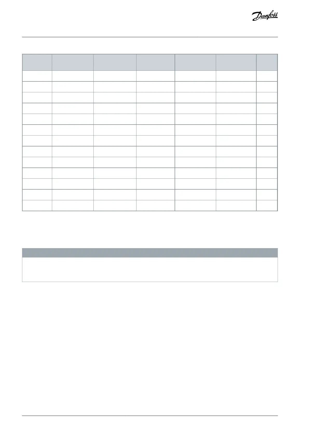
Table 72: Recommended Fuse Ratings for UL Installation, 525–600 V
Maximum fuse
rating F1 [A]
Minimum volt-
age rating [V]
5.10 Enabling Motor Operation
If the status line at the bottom of the LCP reads AUTO REMOTE COAST, the unit is ready to operate but is missing an input signal
from terminal XD2.14 in the control compartment. Digital input terminal XD2.14 is designed to receive a 24 V DC external interlock
command that allows the drive to operate when using factory default programming values.
N O T I C E
FACTORY-INSTALLED OPTIONAL EQUIPMENT
Do not remove factory-installed wiring to terminal XD2.14. If the drive does not run, refer to the documentation for the optional
equipment that is wired into terminal XD2.14.
Procedure
When no interlock device is used, use a push-in type jumper (WAGO 2002-433) between terminal XD2.11 and XD2.14 in the
control compartment. This wire provides an internal 24 V signal on terminal XD2.14. The drive is ready for operation.
5.11 Selecting the Voltage/Current Input Signal
The analog input terminals XD2.7 and XD2.8 in the control compartment allow setting of input signal to voltage (0–10 V) or current
(0/4–20 mA).
Terminal XD2.7: Speed reference signal in open loop (see parameter 16-61 Terminal 53 Switch Setting).
Terminal XD2.8: Feedback signal in closed loop (see parameter 16-63 Terminal 54 Switch Setting).
Procedure
Disconnect power to the drive.
Remove the LCP (local control panel).
Remove any optional equipment covering the switches.
AQ262139143212en-000301 / 130R0879110 | Danfoss A/S © 2021.10
Electrical Installation
VLT® AutomationDrive FC 302
Operating Guide
 Loading...


