4.
1.
2.
3.
1.
1.
Select the baud rate in parameter 8-32 Baud Rate.
Example
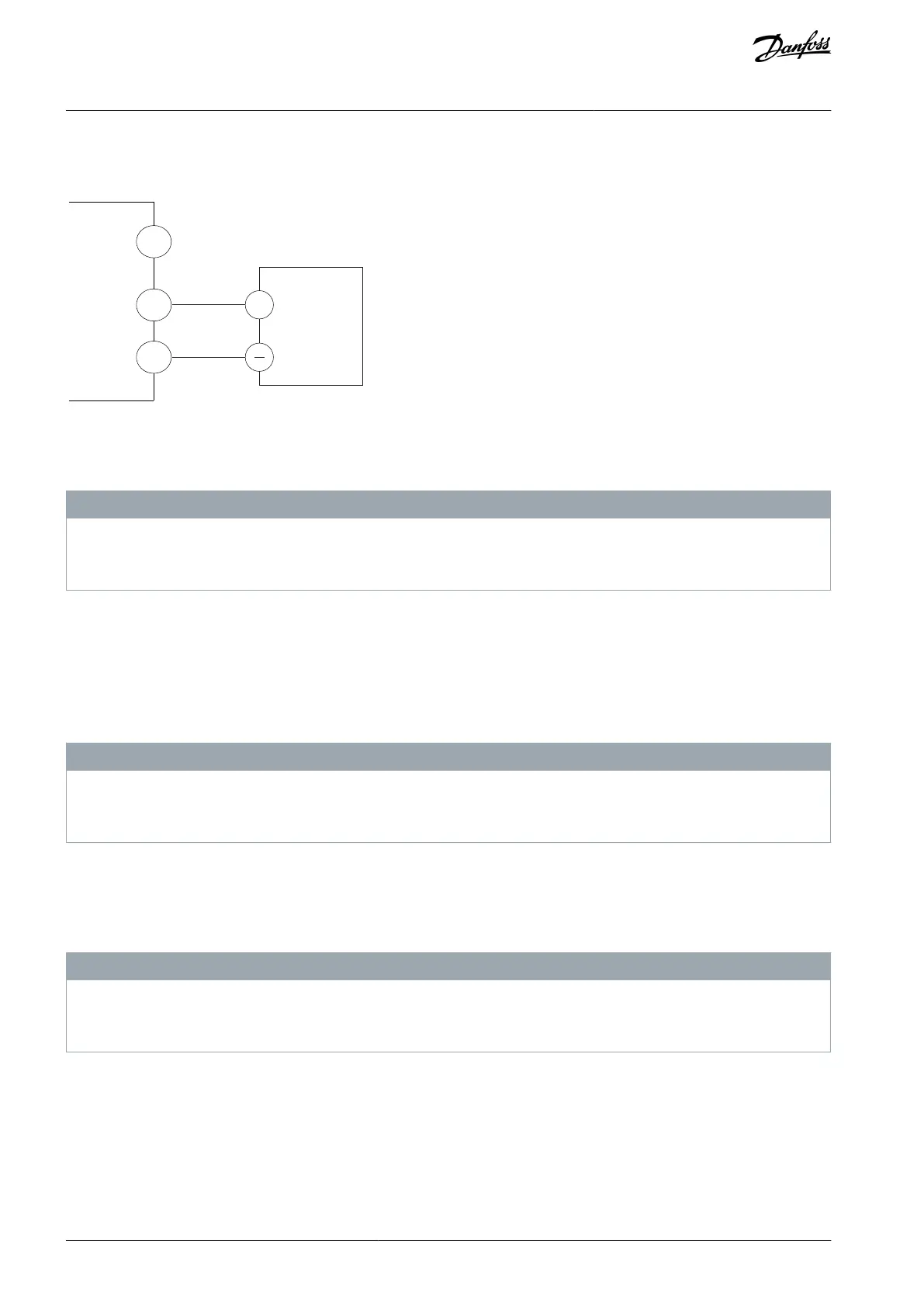
Illustration 63: RS485 Wiring Connection
5.13 Configuring the Passive Harmonic Filter (PHF)
N O T I C E
EQUIPMENT DAMAGE
Failure to use the correct settings can result in the AC drive overheating, resulting in damage to the AC drive and its surround-
ings.
Procedure
Set parameter 5-02 Terminal 29 Mode to [1] Output.
Set parameter 5-31 Terminal 29 to [188] AHF Capacitor Connect.
Set parameter 14-51 DC-link Compensation to [0] Off.
5.14 Configuring the dU/dt Filter
N O T I C E
EQUIPMENT DAMAGE
Failure to use the correct settings for the D9h and D10h enclosures can result in the AC drive overheating, resulting in damage to
the AC drive and its surroundings. E5h and E6h enclosures are not required to use a specific setting.
Procedure
Set parameter 14-52 Output Filter to [3] 100%.
5.15 Configuring the Sine-wave Filter
N O T I C E
EQUIPMENT DAMAGE
Failure to use the correct settings can result in the AC drive overheating, resulting in damage to the AC drive and its surround-
ings.
Procedure
Set parameter 14-55 Output Filter to [1] Sine-wave.
5.16 MCCB Configuration
The molded-case circuit breaker (MCCB) offers the following trip settings:
AQ262139143212en-000301 / 130R0879112 | Danfoss A/S © 2021.10
Electrical Installation
VLT® AutomationDrive FC 302
Operating Guide
 Loading...


