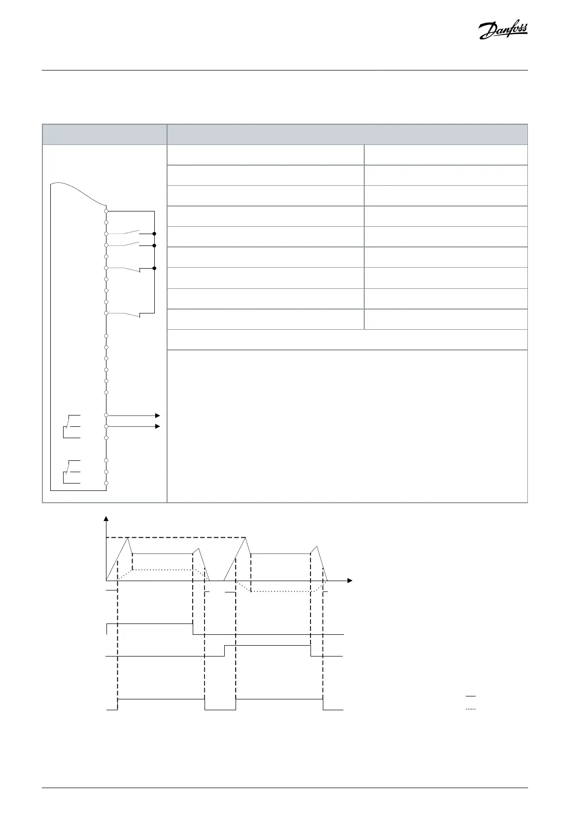
8.1.13 Wiring Configuration: Mechanical Brake Control
Table 94: Wiring Configuration for Mechanical Brake Control
D IN
D IN
D IN
+10 V
A IN
A IN
COM
A OUT
COM
R 1 R 2
e30bu093.10
XD2.16
XD2.17
XD2.19
XD2.6
XD2.7
XD2.8
XD2.9
XD2.5
XD2.4
XD2.21
XD2.22
XD2.23
XD2.24
XD2.25
XD2.26
Parameter 5-40 Function Relay
Parameter 5-10 Terminal 18 Digital Input
Parameter 5-11 Terminal 19 Digital Input
Parameter 1-71 Start Delay
Parameter 1-72 Start Function
Parameter 1-76 Start Current
Parameter 2-20 Release Brake Current
Parameter 2-21 Activate Brake Speed [RPM]
Half of nominal slip of the motor
Notes/comments:
Terminal 18 in the parameter title corresponds to terminal XD2.12 in the control compartment.
Terminal 19 in the parameter title corresponds to terminal XD2.13 in the control compartment.
Illustration 70: Mechanical Brake Control
AQ262139143212en-000301 / 130R0879134 | Danfoss A/S © 2021.10
Wiring Configuration Examples
VLT® AutomationDrive FC 302
Operating Guide
 Loading...


