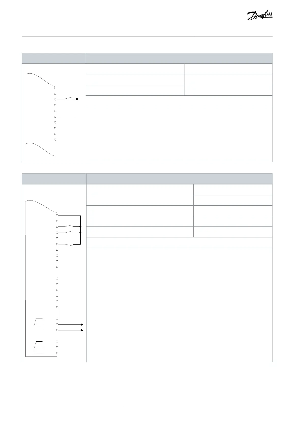
Table 84: Wiring Configuration for Run/Stop Command without External Interlock
+24 V
+24 V
D IN
D IN
D IN
COM
D IN
D IN
D IN
D IN
e30bu082.10
XD2.10
XD2.11
XD2.12
XD2.13
XD2.18
XD2.14
XD2.15
XD2.16
XD2.17
XD2.19
Parameter 5-10 Terminal 18 Digital Input
Parameter 5-12 Terminal 27 Digital Input
Notes/comments:
If parameter 5-12 Terminal 27 Digital Inputs is set to [0] No operation, a jumper wire to terminal
XD2.14 is not needed.
D IN 37 is an option.
Terminal 18 in the parameter title corresponds to terminal XD2.12 in the control compartment.
Terminal 27 in the parameter title corresponds to terminal XD2.14 in the control compartment.
Table 85: Wiring Configuration for Run Permissive
A IN
A IN
COM
A OUT
COM
R1
R2
XD2.16
XD2.17
XD2.19
XD2.6
XD2.7
XD2.8
XD2.9
XD2.5
XD2.4
XD2.21
XD2.22
XD2.23
XD2.24
XD2.25
XD2.26
Parameter 5-10 Terminal 18 Digital Input
Parameter 5-11 Terminal 19 Digital Input
Parameter 5-12 Terminal 27 Digital Input
Parameter 5-40 Function Relay
Notes/comments:
D IN 37 is an option.
Terminal 18 in the parameter title corresponds to terminal XD2.12 in the control compartment.
Terminal 19 in the parameter title corresponds to terminal XD2.13 in the control compartment.
Terminal 27 in the parameter title corresponds to terminal XD2.14 in the control compartment.
AQ262139143212en-000301 / 130R0879128 | Danfoss A/S © 2021.10
Wiring Configuration Examples
VLT® AutomationDrive FC 302
Operating Guide
 Loading...


