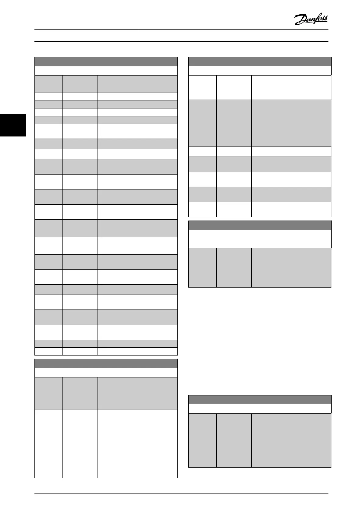
13-10 Comparator Operand
Option: Function:
[3] Motor speed [RPM] or [Hz], as set in
parameter 0-02 Motor Speed Unit.
[4] Motor Current
[5] Motor torque
[6] Motor power
[7] Motor voltage
[8] DC-link
voltage
[9] Motor Thermal Value is in percent.
[10] Drive thermal Value is in percent.
[11] Heat sink
temp.
Value is in percent.
[12] Analog input
AI53
Value is in percent.
[13] Analog input
AI54
Value is in percent.
[14] Analog input
AIFB10
AIFB10 is internal 10 V supply.
[15] Analog input
AIS24V
AIS24V is a 24 V switch mode
power supply.
[17] Analog input
AICCT
Value is in [°]. AICCT is control card
temperature.
[18] Pulse input
FI29
Value is in percent.
[19] Pulse input
FI33
Value is in percent.
[20] Alarm number The number of registered alarms.
[21] Warning
number
[22] Analog input
x30 11
[23] Analog input
x30 12
[30] Counter A
[31] Counter B
13-11 Comparator Operator
Option: Function:
Select the operator to be used in
the comparison. This is an array
parameter containing comparator
operators 0–5.
[0] < The result of the evaluation is true
when the variable selected in
parameter 13-10 Comparator
Operand is smaller than the xed
value in
parameter 13-12 Comparator Value.
The result is false if the variable
selected in
parameter 13-10 Comparator
13-11 Comparator Operator
Option: Function:
Operand is greater than the xed
value in
parameter 13-12 Comparator Value.
[1] ≈ (equal) The result of the evaluation is true
when the variable selected in
parameter 13-10 Comparator
Operand is approximately equal to
the xed value in
parameter 13-12 Comparator Value.
[2] > Inverse logic of option [0] <.
[5] TRUE longer
than..
[6] FALSE longer
than..
[7] TRUE shorter
than..
[8] FALSE shorter
than..
13-12 Comparator Value
Array [6]
Range: Function:
Size
related*
[-100000 -
100000 ]
Enter the trigger level for the
variable that is monitored by this
comparator. This is an array
parameter containing comparator
values 0–5.
4.12.3 13-2* Timers
Use the result (true or false) from timers directly to dene
an event (see parameter 13-51 SL Controller Event), or as
boolean input in a logic rule (see parameter 13-40 Logic
Rule Boolean 1, parameter 13-42 Logic Rule Boolean 2, or
parameter 13-44 Logic Rule Boolean 3). A timer is only false
when started by an action (for example [29] Start timer 1)
until the timer value entered in this parameter has elapsed.
Then it becomes true again.
All parameters in this parameter group are array
parameters with index 0–2. Select index 0 to program
timer 0, select index 1 to program timer 1, and so on.
13-20 SL Controller Timer
Range: Function:
Size
related*
[ 0 - 0] Enter the value to dene the
duration of the false output from
the programmed timer. A timer is
only false if it is started by an
action (that is [29] Start timer 1) and
until the given timer value has
elapsed.
Parameter Descriptions VLT® AutomationDrive FC 361
120 Danfoss A/S © 03/2019 All rights reserved. MG06J202
44