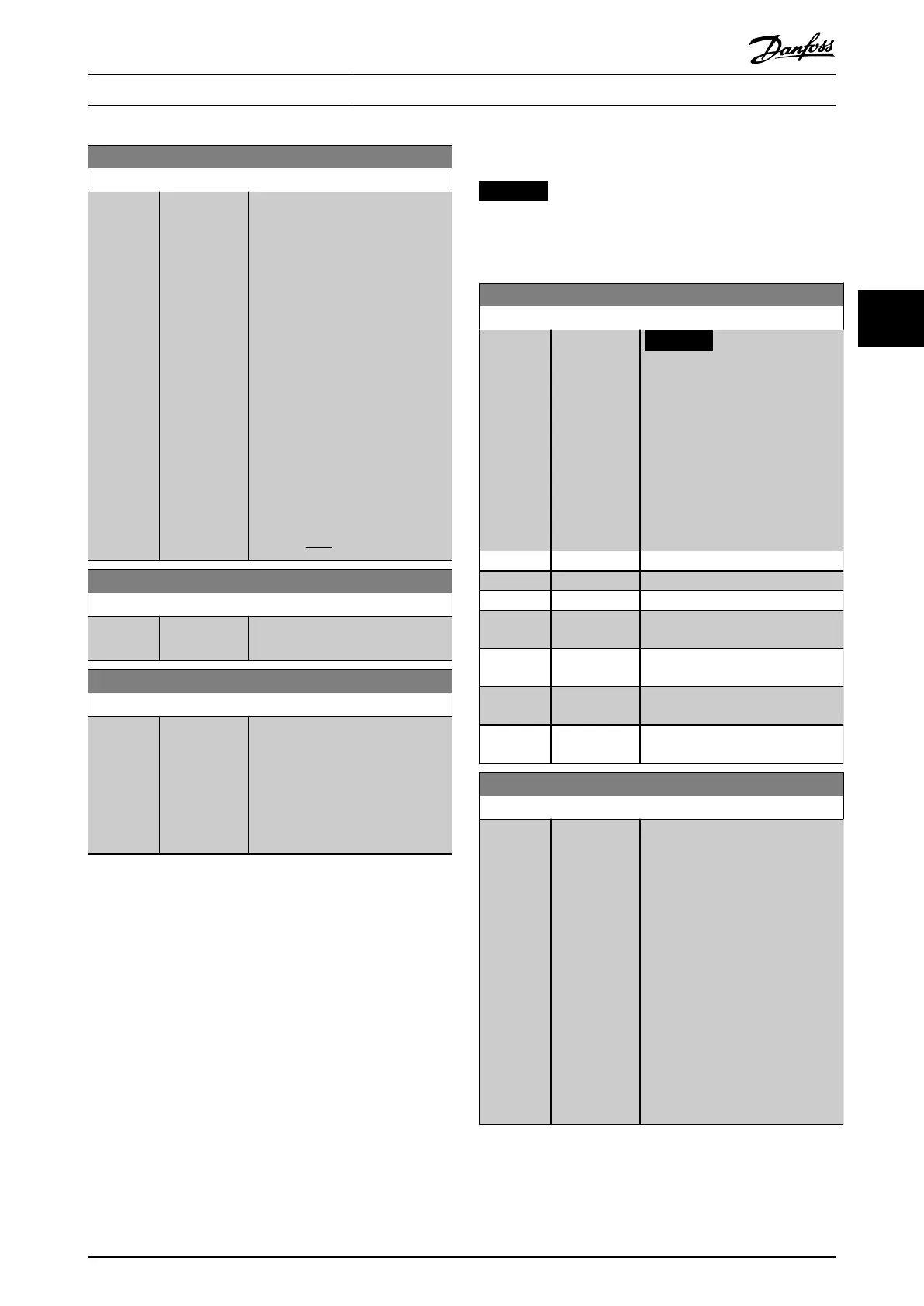
6-62 Terminal X30/8 Max. Scale
Range: Function:
100 %* [0 - 200 %] Scales the maximum output of the
selected analog signal on terminal
X30/8. Scale the value to the
required maximum value of the
current signal output. Scale the
output to give a lower current than
20 mA at full scale or 20 mA at an
output below 100% of the
maximum signal value. If 20 mA is
the required output current at a
value between 0–100% of the full-
scale output, program the
percentage value in the parameter,
that is 50% = 20 mA. If a current 4–
20 mA is required at maximum
output (100%), calculate the
percentage value as follows:
20mA/desiredmaximumcurrentx100 %
i . e . 10mA:
20 − 4
10
x100 = 160 %
6-63 Terminal X30/8 Bus Control
Range: Function:
0 %* [0 - 100 %] Holds the level of output X30/8 if
controlled by bus.
6-64 Terminal X30/8 Output Timeout Preset
Range: Function:
0 %* [0 - 100 %] Holds the preset level of output
X30/8.
If there is a eldbus timeout and a
timeout function is selected in
parameter 6-60 Terminal X30/8
Output, the output is preset to this
level.
4.8 Parameters: 7-** Controllers
NOTICE
If separate encoders are used, adjust the ramp-related
parameters according to the gear ratio between the 2
encoders.
7-00 Speed PID Feedback Source
Option: Function:
NOTICE
This parameter cannot be
adjusted while the motor is
running.
Select the encoder for closed-loop
feedback.
The feedback may come from a
dierent encoder (typically
mounted on the application itself)
than the motor-mounted encoder.
[1] * 24V encoder
[2] MCB 102
[3] MCB 103
[6] Analog Input
53
[7] Analog Input
54
[8] Frequency
input 29
[9] Frequency
input 33
7-02 Speed PID Proportional Gain
Range: Function:
Size
related*
[0 - 1] Enter the speed controller propor-
tional gain. The proportional gain
amplies the error (that is, the
deviation between the feedback
signal and the setpoint). This
parameter is used with
parameter 1-00 Conguration Mode
[0] Speed open loop and [1] Speed
closed loop control. Quick control is
obtained at high amplication.
Increasing amplication makes the
process less stable.
Use this parameter for values with 3
decimals. For values with 4
decimals, use parameter 3-83 Quick
Stop S-ramp Ratio at Decel. Start.
Parameter Descriptions Programming Guide
MG06J202 Danfoss A/S © 03/2019 All rights reserved. 87
4 4
 Loading...


