1 Introduction
1.1 How to Read This Programming Guide
1.1.1 Purpose of the Manual
This programming guide provides information about
controlling the frequency converter, parameter access,
programming, and troubleshooting.
The programming guide is intended for use by
qualied
personnel who are familiar with VLT
®
AutomationDrive FC
361.
Read the instructions before programming and follow the
procedures in this manual.
VLT
®
is a registered trademark.
1.1.2 Additional Resources
Additional resources include:
•
VLT
®
AutomationDrive FC 361 Operating Guide
provides the necessary information for getting
the frequency converter up and running.
•
VLT
®
AutomationDrive FC 361 Design Guide
provides detailed technical information about the
frequency converter and customer design and
applications.
Contact the local Danfoss supplier for the documentation.
1.1.3 Document and Software Version
This manual is regularly reviewed and updated. All
suggestions for improvement are welcome. Table 1.1 shows
the document version and the corresponding software
version.
Edition Remarks
Software
version
MG06J2
Update parameter descriptions and
manual cover.
1.0x
Table 1.1 Document and Software Version
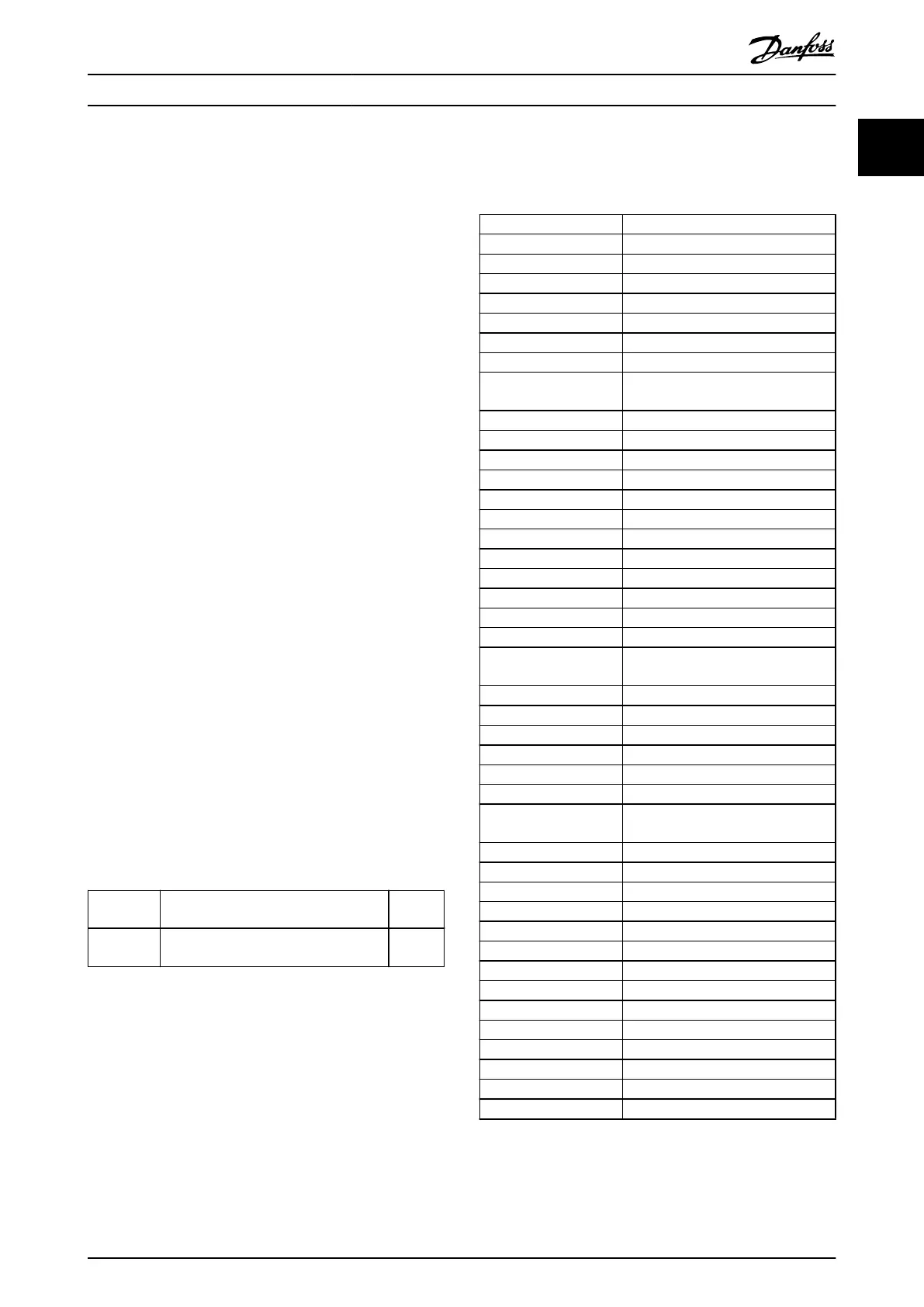
°C
Degrees Celsius
°F
Degrees Fahrenheit
AC Alternating current
AEO Automatic energy optimization
ACP Application control processor
AWG American wire gauge
AMA Automatic motor adaptation
DC Direct current
EEPROM
Electrically erasable programmable
read-only memory
EMC Electromagnetic compatibility
EMI Electromagnetic interference
ESD Electrostatic discharge
ETR Electronic thermal relay
f
M,N
Nominal motor frequency
FC Frequency converter
IGBT Insulated-gate bipolar transistor
IP Ingress protection
I
LIM
Current limit
I
INV
Rated inverter output current
I
M,N
Nominal motor current
I
VLT,MAX
Maximum output current
I
VLT,N
Rated output current supplied by the
frequency converter
L
d
Motor d-axis inductance
L
q
Motor q-axis inductance
LCP Local control panel
LED Light-emitting diode
MCP Motor control processor
N.A. Not applicable
NEMA
National Electrical Manufacturers
Association
P
M,N
Nominal motor power
PCB Printed circuit board
PE Protective earth
PELV Protective extra low voltage
PWM Pulse width modulation
R
s
Stator resistance
Regen Regenerative terminals
RPM Revolutions per minute
RFI Radio frequency interference
SCR Silicon controlled rectier
SMPS Switch mode power supply
T
LIM
Torque limit
U
M,N
Nominal motor voltage
X
h
Motor main reactance
Table 1.2 Abbreviations
Introduction Programming Guide
MG06J202 Danfoss A/S © 03/2019 All rights reserved. 3
1 1
 Loading...


