Parameter set-up:
•
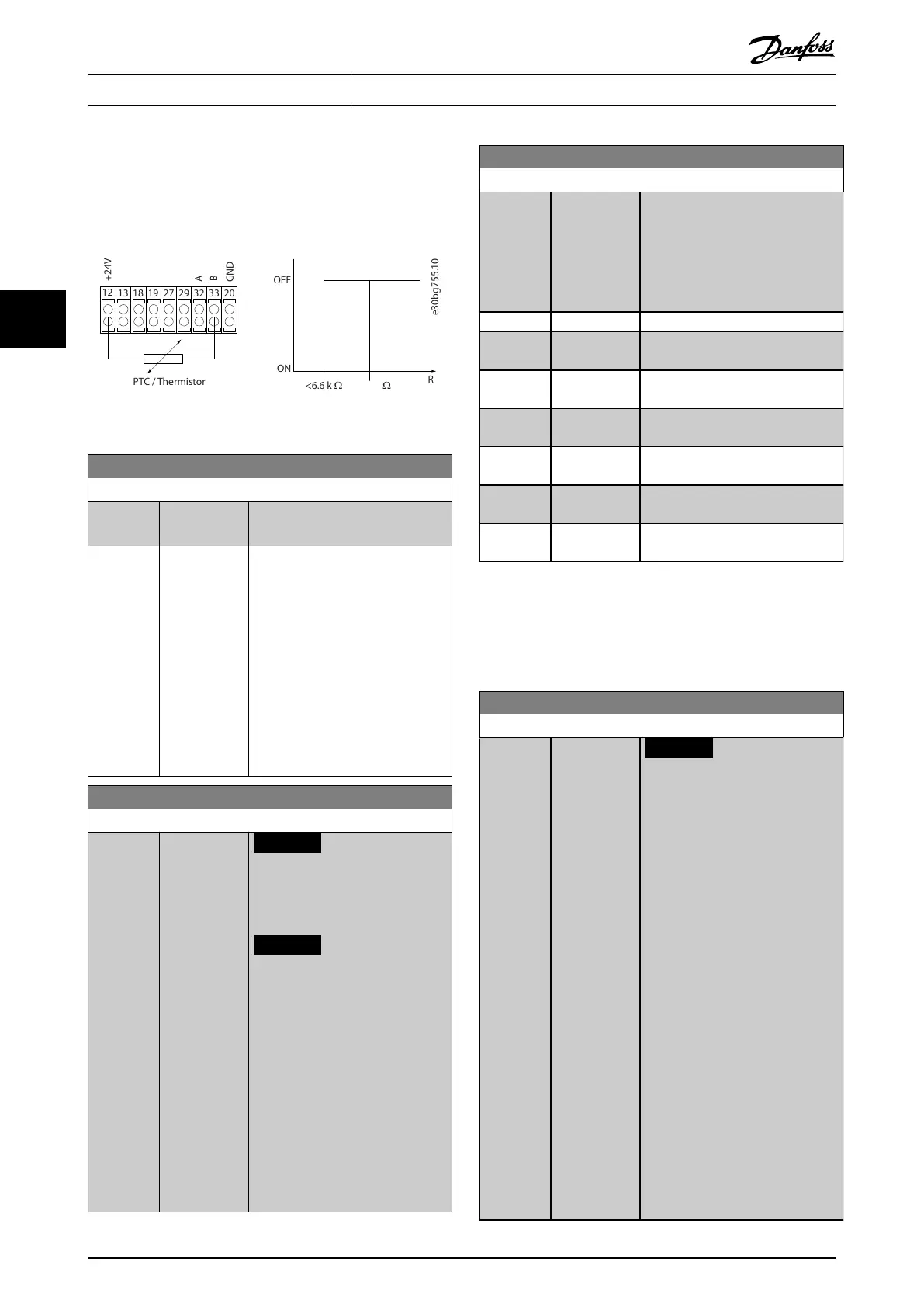
Set parameter 1-90 Motor Thermal Protection to [2]
Thermistor Trip.
•
Set parameter 1-93 Thermistor Source to [6] Digital
Input.
Illustration 4.13 Thermistor Connection
1-91 Motor External Fan
Option: Function:
[0] * No No external fan is required, that is
the motor is derated at low speed.
[1] Yes Applies an external motor fan
(external ventilation), so no
derating of the motor is required at
low speed. The upper curve in
Illustration 4.12 (f
out
= 1 x f
M,N
) is
followed if the motor current is
lower than nominal motor current
(see parameter 1-24 Motor Current).
If the motor current exceeds
nominal current, the operation time
still decreases as if no fan was
installed.
1-93 Thermistor Source
Option: Function:
NOTICE
This parameter cannot be
adjusted while the motor is
running.
NOTICE
Set digital input to [0] PNP -
Active at 24 V in
parameter 5-00 Digital I/O
Mode.
Select the input to which the
thermistor (PTC sensor) should be
connected. An analog input option
[1] Analog Input 53 or [2] Analog
Input 54 cannot be selected if the
analog input is already in use as a
reference source (selected in
parameter 3-15 Reference 1 Source,
1-93 Thermistor Source
Option: Function:
parameter 3-16 Reference 2 Source,
or parameter 3-17 Reference 3
Source).
When using VLT
®
PTC Thermistor
Card MCB 112, always select [0]
None.
[0] * None
[1] Analog Input
53
[2] Analog Input
54
[3] Digital input
18
[4] Digital input
19
[5] Digital input
32
[6] Digital input
33
4.3 Parameters: 2-** Brakes
4.3.1 2-0* DC brakes
Parameter group for conguring the DC brake and DC hold
functions.
2-00 DC Hold Current
Range: Function:
50 %* [ 0 - 160 %]
NOTICE
The maximum value depends
on the rated motor current.
Avoid 100% current for too
long. It may damage the
motor.
Low values of DC hold
produce larger than expected
currents with larger motor
power sizes. This error
increases as the motor power
increases.
Enter a value for holding current as
a percentage of the rated motor
current I
M,N
set in
parameter 1-24 Motor Current. 100%
DC hold current corresponds to I
M,N
.
This parameter holds the motor
function (holding torque) or
preheats the motor.
This parameter is active if DC hold
is selected in parameter 1-72 Start
Function [0] or
parameter 1-80 Function at Stop [1].
Parameter Descriptions VLT® AutomationDrive FC 361
48 Danfoss A/S © 03/2019 All rights reserved. MG06J202
44
 Loading...


