3.1.1 LCD Display
The display has backlight and a total of 6 alpha-numeric
lines. The display lines show the direction of rotation
(arrow), the selected set-up, and the programming set-up.
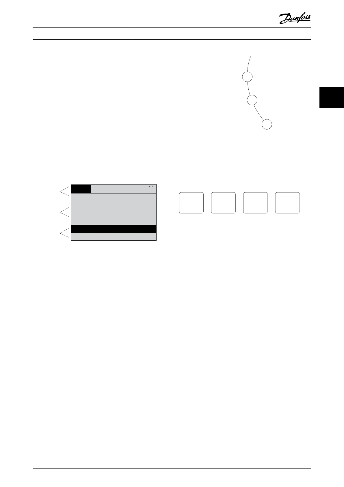
The display is divided into 3 sections.
Top section
The top section shows up to 2 measurements in normal
operating status.
Middle section
The top line shows up to 5 measurements with related
unit, regardless of status (except in the case of alarm/
warning).
Bottom section
The bottom section always shows the state of the
frequency converter in Status mode.
Top section
Middle section
Bottom section
Status
43 RPM
1.4 Hz
Auto Remote Running
! Pwr.card temp (W29)
2.9%
5.44 A 25.3kW
1(1)
130BP074.10
!
Illustration 3.2 Display
The active set-up (selected as the active set-up in
parameter 0-10 Active Set-up) is shown. When programming
another set-up than the active set-up, the number of the
programmed set-up appears to the right.
Display contrast adjustment
Press [Status] and [
▲
] for darker display.
Press [Status] and [
▼
] for brighter display.
Most parameter set-ups can be changed immediately via
the LCP, unless a password has been created via
parameter 0-60 Main Menu Password or via
parameter 0-65 Quick Menu Password.
Indicator lights
If certain threshold values are exceeded, the alarm and/or
warning indicator lights up. A status and alarm text appear
on the LCP.
The ON indicator light is activated when the frequency
converter receives mains voltage or via a DC bus terminal
or 24 V external supply. At the same time, the back
indicator light is on.
•
Green LED/On: Control section is working.
•
Yellow LED/Warn: Indicates a warning.
•
Flashing Red LED/Alarm: Indicates an alarm.
Illustration 3.3 Indicator Lights
LCP keys
The control keys are divided into functions. The keys below
the display and indicator lights are used for parameter set-
up, including option of display indication during normal
operation.
130BP045.10
Status
Quick
Menu
Main
Menu
Alarm
Log
Illustration 3.4 LCP Keys
[Status]
Indicates the status of the frequency converter and/or the
motor. Select between 3 dierent readouts by pressing
[Status]: 5 line readouts, 4 line readouts, or smart logic
control.
Press [Status] for selecting the mode of display or for
changing back to display mode from either the quick
menu mode, the main menu mode, or the alarm mode.
Also use [Status] to toggle single or double readout mode.
[Quick Menu]
Allows quick access to dierent quick menus such as:
•
My personal menu.
•
Quick set-up.
•
Changes made.
•
Loggings.
Press [Quick Menu] to program the parameters belonging
to the Quick Menu. It is possible to switch directly
between quick menu mode and main menu mode.
[Main Menu]
Is used for programming all parameters.
It is possible to switch directly between main menu mode
and quick menu mode.
Parameter shortcut can be carried out by pressing down
[Main Menu] for 3 s. The parameter shortcut allows direct
access to any parameter.
Programming Programming Guide
MG06J202 Danfoss A/S © 03/2019 All rights reserved. 13
3 3
 Loading...


