4.7 Parameters: 6-** Analog In/Out
4.7.1 6-0* Analog I/O Mode
The analog inputs can be allocated to be either voltage (0–
10 V) or current input (0/4–20 mA).
NOTICE
Thermistors may be connected to either an analog or a
digital input.
6-00 Live Zero Timeout Time
Range: Function:
10 s* [0 - 99 s] Enter the live zero timeout in s. Live
zero timeout time is active for
analog inputs, that is terminal 53 or
terminal 54, used as reference or
feedback sources.
If the reference signal value
associated with the selected current
input drops below 50% of the value
set in:
•
Parameter 6-10 Terminal 53
Low Voltage
•
Parameter 6-12 Terminal 53
Low Current
•
Parameter 6-20 Terminal 54
Low Voltage
•
Parameter 6-22 Terminal 54
Low Current
for a time period longer than the
time set in parameter 6-00 Live Zero
Timeout Time, the function selected
in parameter 6-01 Live Zero Timeout
Function is activated.
6-01 Live Zero Timeout Function
Option: Function:
Select the timeout function. If the
input signal on terminal 53 or 54 is
below 50% of the value in
•
Parameter 6-10 Terminal 53
Low Voltage
•
Parameter 6-12 Terminal 53
Low Current
•
Parameter 6-20 Terminal 54
Low Voltage
•
Parameter 6-22 Terminal 54
Low Current
for a time period dened in
parameter 6-00 Live Zero Timeout
Time, then the function set in
6-01 Live Zero Timeout Function
Option: Function:
parameter 6-01 Live Zero Timeout
Function is activated.
If several timeouts occur simulta-
neously, the frequency converter
prioritizes the timeout functions as
follows:
1. Parameter 6-01 Live Zero
Timeout Function.
2. Parameter 8-04 Control
Word Timeout Function.
[0] * O
[1] Freeze output Frozen at the present value.
[2] Stop Overruled to stop.
[3] Jogging Overruled to jog speed.
[4] Max. speed Overruled to maximum speed.
[5] Stop and trip Overruled to stop with subsequent
trip.
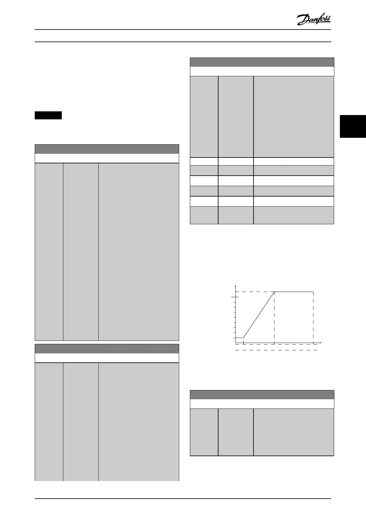
4.7.2 6-1* Analog Input 1
Parameters for conguring the scaling and limits for analog
input 1 (terminal 53).
Ex. 5 V 10 V
300
600
900
1200
1500
150
130BT103.10
1 V
Par 6-xx
'Low Voltage'or
'Low Current'
Par 6-xx
'High Voltage'or
'High Current'
Analog input
Ref./Feedback
[RPM]
Par 6-xx
'High Ref./
Feedb. Value'
Par 6-xx
'Low Ref./
Feedb. Value'
Illustration 4.32 Analog Input 1
6-10 Terminal 53 Low Voltage
Range: Function:
0.07 V* [ 0 - par. 6-11
V]
Enter the low voltage value. This
analog input scaling value should
correspond to the minimum
reference value set in
parameter 6-14 Terminal 53 Low Ref./
Feedb. Value.
Parameter Descriptions Programming Guide
MG06J202 Danfoss A/S © 03/2019 All rights reserved. 81
4 4
 Loading...


