0.6
0.6
f
g
= 10 Hz
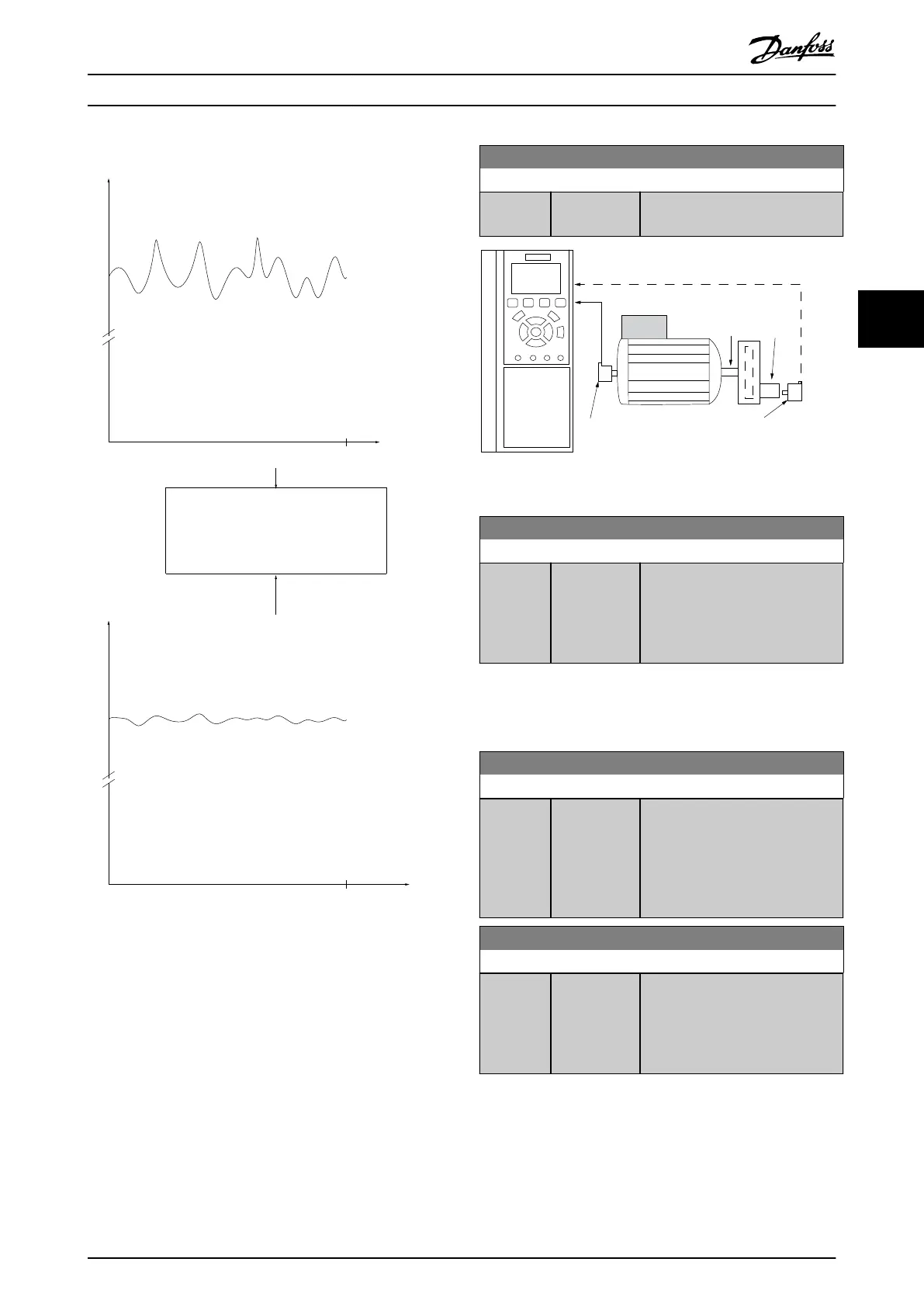
175ZA293.11
Feedback
Disturbed feedback signal
t (Sec.)
t (Sec.)
Filtered feedback signal
Lowpass lter
Feedback
Illustration 4.34 Feedback Signal
7-07 Speed PID Feedback Gear Ratio
Range: Function:
1* [ 0.0001 -
32.0000]
The frequency converter multiplies
the speed feedback by this ratio.
Par 7-07=1.00 Par 7-07=n1/n2
130BA871.10
Motor
n1 n2
Illustration 4.35 Speed PID Feedback Gear Ratio
7-08 Speed PID Feed Forward Factor
Range: Function:
0 %* [0 - 500 %] The reference signal bypasses the
speed controller by the amount
specied. This feature increases the
dynamic performance of the speed
control loop.
4.8.1 7-1* Torque PI Control
Parameters for conguring the torque PI control.
7-12 Torque PI Proportional Gain
Range: Function:
100 %* [0 - 500 %] Enter the proportional gain value
for the torque controller. Selection
of a high value makes the
controller react faster. Too high a
setting leads to controller
instability.
7-13 Torque PI Integration Time
Range: Function:
0.020 s* [0.002 - 2 s] Enter the integration time for the
torque controller. Selection of a low
value makes the controller react
faster. Too low a setting leads to
controller instability.
Parameter Descriptions Programming Guide
MG06J202 Danfoss A/S © 03/2019 All rights reserved. 89
4 4
 Loading...


