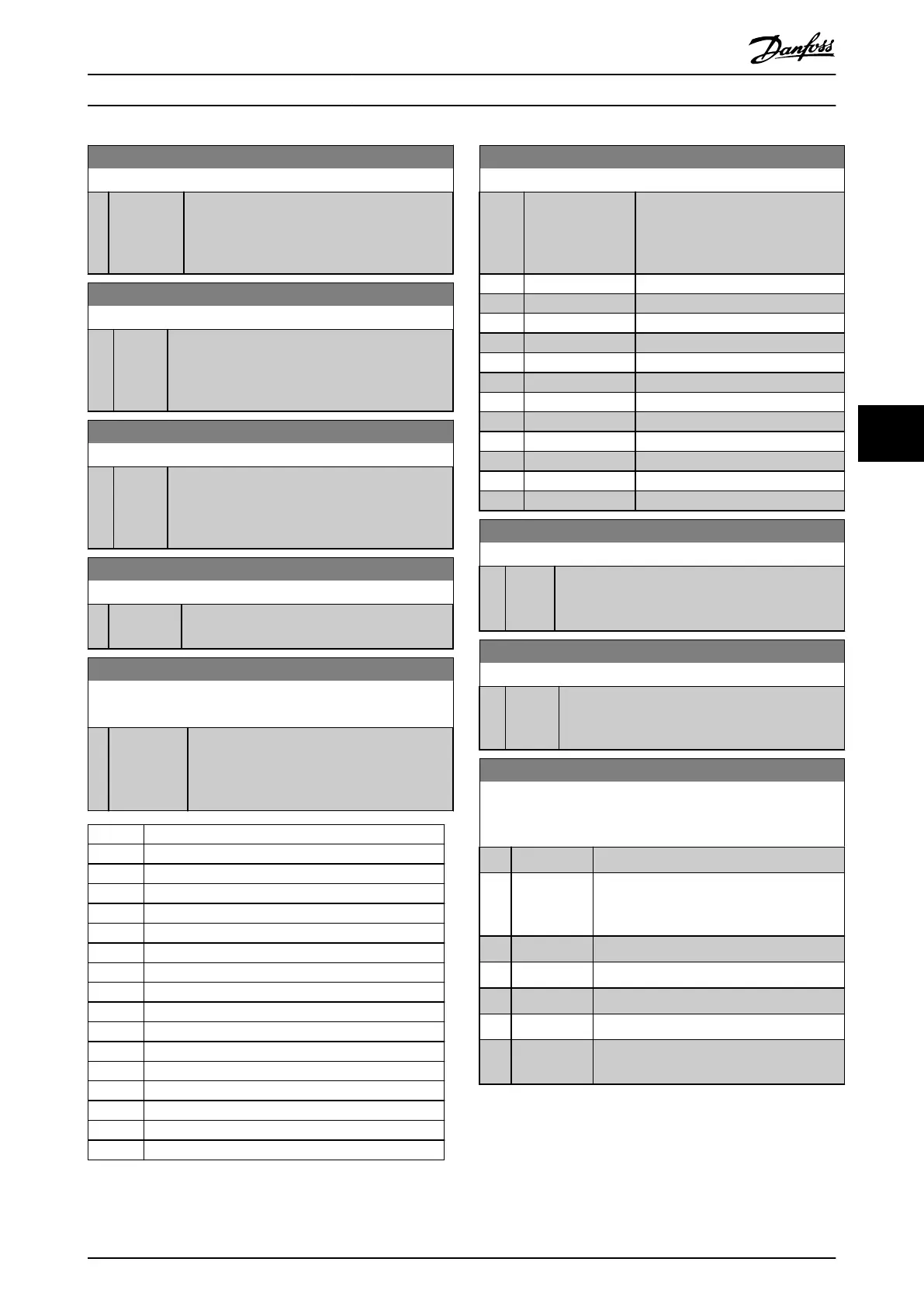
9-44 Fault Message Counter
Range: Function:
0* [0 -
65535 ]
Indicates the number of fault events presently
stored in parameter 9-45 Fault Code. The buer
capacity is maximum 8 error events. The buer
and counter are set to 0 by reset or power-up.
9-45 Fault Code
Range: Function:
0* [0 - 0 ] This buer contains the alarm word for all alarms
and warnings that have occurred since last reset or
power-up. The buer capacity is maximum 8 error
events.
9-47 Fault Number
Range: Function:
0* [0 - 0 ] This buer contains the alarm word for all alarms
and warnings that have occurred since last reset or
power-up. The buer capacity is maximum 8 error
events.
9-52 Fault Situation Counter
Range: Function:
0* [0 - 1000 ] Indicates the number of fault events that have
occurred since last reset or power-up.
9-53 Probus Warning Word
Read only
Range: Function:
0* [0 - 65535 ] This parameter shows PROFIBUS communi-
cation warnings. Refer to the VLT
®
PROFIBUS DP
MCA 101 Installation Guide for further
information.
Bit Description
0 Connection with DP-master is not OK.
1 Not used.
2 FDL (eldbus data link layer) is not OK.
3 Clear data command received.
4 Actual value is not updated.
5 Baud rate search.
6 PROFIBUS ASIC is not transmitting.
7 Initialization of PROFIBUS is not OK.
8 Frequency converter is tripped.
9 Internal CAN error.
10 Wrong conguration data from PLC.
11 Wrong ID sent by PLC.
12 Internal fault occurred.
13 Not congured.
14 Timeout active.
15 Warning 34, Fieldbus fault active.
Table 6.1 PROFIBUS Warning Word
9-63 Actual Baud Rate
Option: Function:
This parameter shows the actual
PROFIBUS baud rate. The PROFIBUS
master automatically sets the baud
rate.
[0] 9,6 kbit/s
[1] 19,2 kbit/s
[2] 93,75 kbit/s
[3] 187,5 kbit/s
[4] 500 kbit/s
[6] 1500 kbit/s
[7] 3000 kbit/s
[8] 6000 kbit/s
[9] 12000 kbit/s
[10] 31,25 kbit/s
[11] 45,45 kbit/s
[255] * No baudrate found
9-64 Device Identication
Range: Function:
0* [0 - 0] This parameter shows the device identication.
Refer to the VLT
®
PROFIBUS DP MCA 101 Installation
Guide for further explanation.
9-65 Prole Number
Range: Function:
0* [0 - 0 ] This parameter contains the prole identication.
Byte 1 contains the prole number and byte 2 the
version number of the prole.
9-70 Programming Set-up
This parameter is unique for LCP and eldbus. See
parameter 0-11 Programming Set-up.
Option: Function:
Select the set-up to edit.
[0] Factory setup Uses default data. This option can be used
as a data source to return the other set-ups
to a known state.
[1] Set-up 1 Edits set-up 1.
[2] Set-up 2 Edits set-up 2.
[3] Set-up 3 Edits set-up 3.
[4] Set-up 4 Edits set-up 4.
[9] * Active Set-up Follows the active set-up selected in
parameter 0-10 Active Set-up.
Parameters Programming Guide
MG37G202 Danfoss A/S © 01/2016 All rights reserved. 43
6
6

 Loading...


