SETUP
20
POWERSCAN™ PD/PM96XX
SYSTEM CONNECTIONS
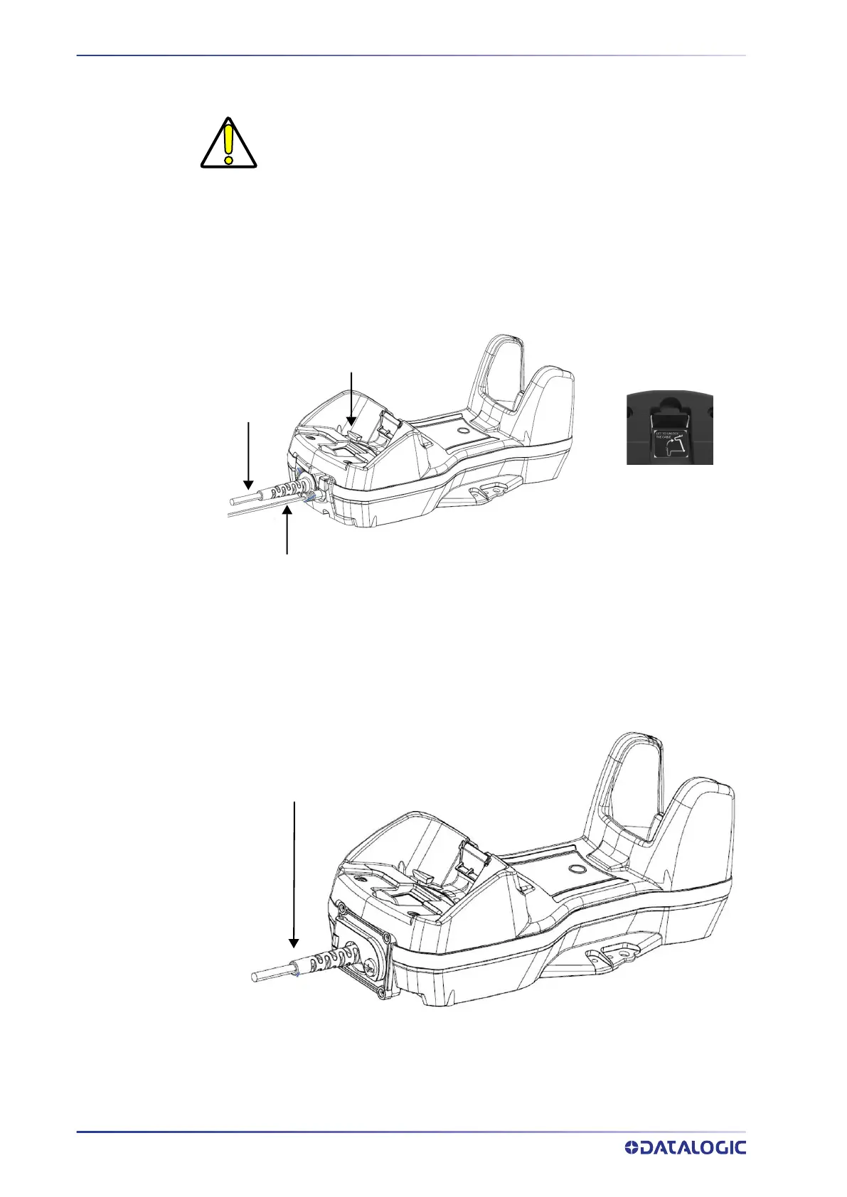
The BC9630 (BC9600 + CM9630 connection module) provides a multi-interface connec-
tor for connections to a host and a power supply connector for an external power sup-
ply.
To unlock the multi-interface cable, first lift the lever and then extract the cable, as indi-
cated by the label next to the lever.
Figure 3 - BC9630 Connection Module
The BC9631 (BC9600 + CM9631 connection module) provides a single multi-interface
connector. Power is supplied by the host (USB) or by an external power supply con-
nected to the cable.
Figure 4 - BC9631 Connection Module
CAUTION: Connections should always be made with power off.
Unlock label
Multi-interface
cable
Power adapter cable
Power adapter + multi-interface cable

 Loading...