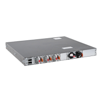
● N3208PX-ON—Up to two external power adapters
● N3224PX-ON, N3248P-ON, and N3248PXE-ON—External power supply connectors to connect the MPS-1S or MPS-3S
shelf
● N3224T-ON, N3248X-ON, and N3248TE-ON—Normal and reverse airflow options
● System ground connector
● Switch-monitoring LEDs
Physical dimensions
The N3200-ON Series switch has the following physical dimensions, excluding the PSU and fan tray handle:
● N3208PX-ON:
○ 43.5 mm x 279.4 mm x 312 mm (H x W x D)
○ 1.71 in x 11 in x 12.28 in (H x W x D)
● All N3200-ON Series switches except the N3208PX-ON:
○ 43.5 mm x 434 mm x 400 mm (H x W x D)
○ 1.71 in x 17.09 in x 15.75 in (H x W x D)
(PSU and fan tray handle adds 30 mm or 1.18 in)
LED display
The N3200-ON Series switch includes LED displays on the I/O and PSU sides of the switch. This section describes open
networking installation environment (ONIE) LED behaviors. Some LED behaviors may change after you install your software.
LED behavior
The following N3200-ON Series switch LED behavior is seen during ONIE operations:
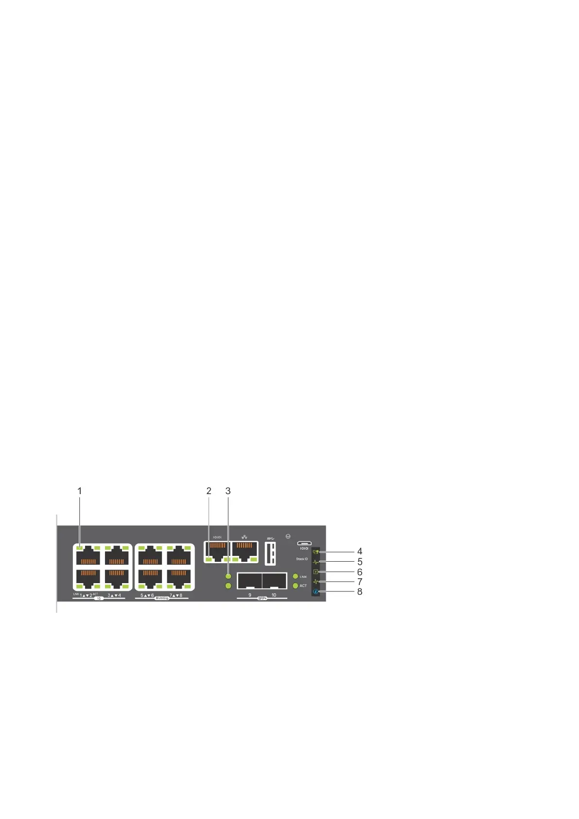
N3208PX-ON LEDs
1.
Link status LEDs 2. Console port LEDs on the left side—management port on
the right side
3. SFP+ port activity LEDs 4. Stack Master ID LED
5. System Status/Health LED 6. Power LED
7. Fan LED 8. Locator LED/System Beacon
14 N3200-ON Series switch
 Loading...