Expansion card installation guidelines
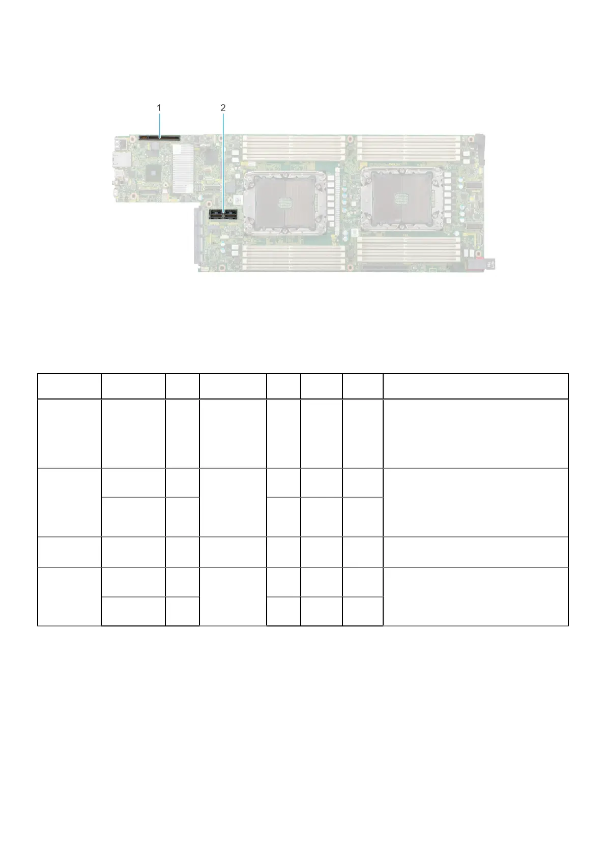
Figure 35. Expansion card slot connectors
1. Riser 1a or Riser 1a with support for SNAP I/O modules (Slot 1)
2. Riser 2b (Slot 2)
The following table describes the expansion card riser configurations:
Table 8. Expansion card riser configurations
Configurati
ons
Expansion
card risers
PCIe
Slots
Controlling
processor
Heigh
t
Length Slot
width
Supported configurations
Config1. with
1x LP
R1a 1 Processor 1
and 2
Low
Profile
Half
length
x16
● 12 x 3.5-inch drives
● 24 x 2.5-inch drives
● 8 x 2.5-inch NVMe drives
● 24 x 2.5-inch NVMe drives
● No backplane
Config2. with
2x LP
R1a 1 Processor 1
and 2
Low
Profile
Half
length
x16
● 12 x 3.5-inch drives
● 24 x 2.5-inch drives
● 8 x 2.5-inch NVMe drives
● 24 x 2.5-inch NVMe drives
● No backplane
R2b 2 Low
Profile
Half
length
x16
Config3. with
1x LP
R1b 1 Processor 1
and 2
Low
Profile
Half
length
x8 + x8
● 8 x 2.5-inch NVMe drives
● No backplane
Config4. with
1x LP
R1b 1 Processor 1
and 2
Low
Profile
Half
length
x8 + x8
● 8 x 2.5-inch NVMe drives
● No backplane
R2b 2 Low
Profile
Half
length
x16
32 Installing and removing system components
 Loading...