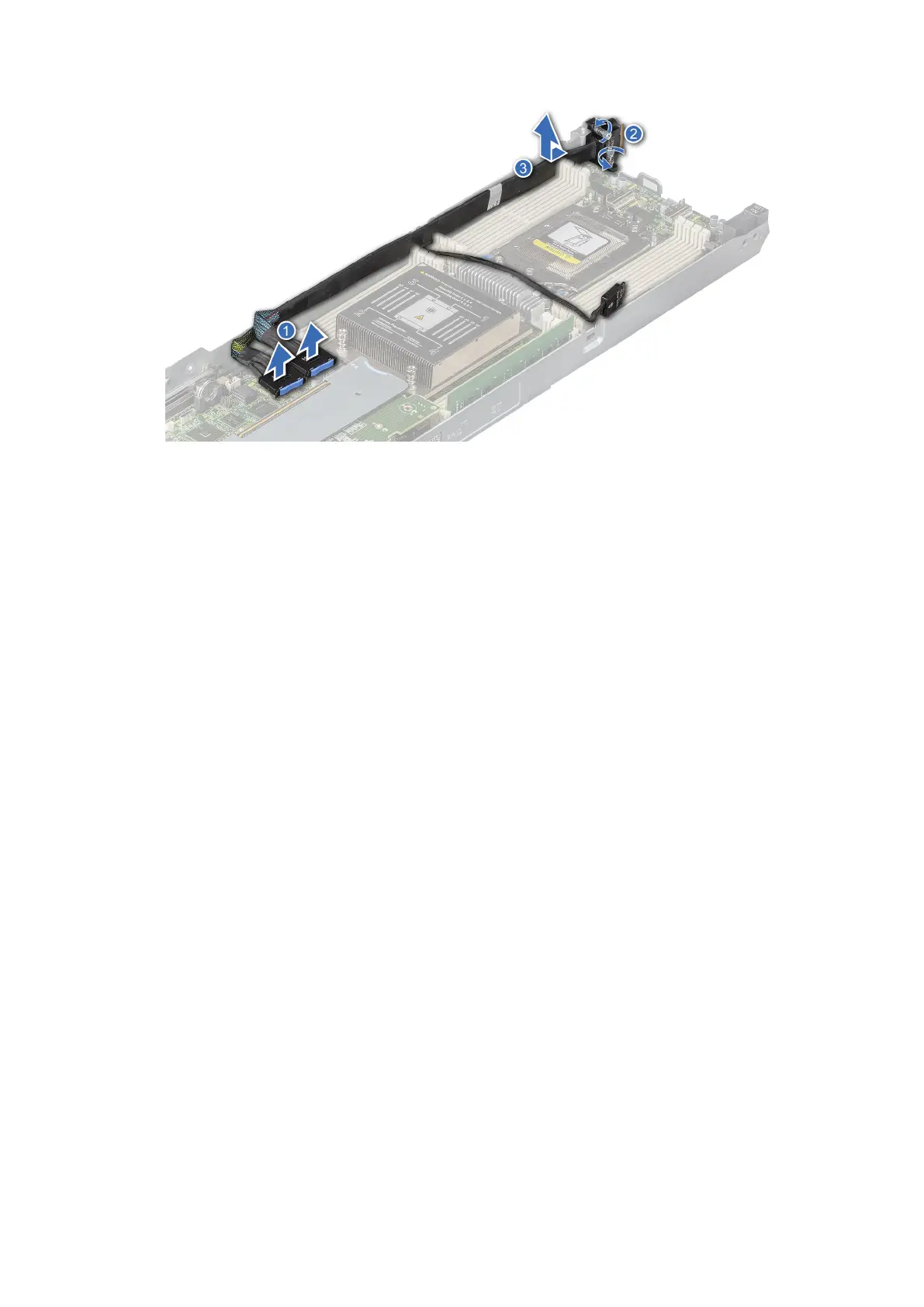
Figure 42. Removing the linking board and SATA cable
5. To disengage the linking board connector, lift and push the MB_cable towards the front of the sled.
6. Remove the MB cable from the sled.
Next steps
1. Install the linking board and PCIe cable.
Installing the linking board and PCIe cable
Prerequisites
1. Follow the safety guidelines listed in Safety instructions.
2. Follow the procedure listed in Before working inside your system.
Steps
1. Route the MB cable along the chassis wall.
2. Align the linking board connector with the screw holes on the chassis and using a Phillips #2 screw driver tighten the captive
screws to secure the linking board cable connector to the chassis.
3. Connect the MB connectors to the connectors on the system board.
48
Installing and removing system components
 Loading...