Table 16. Connector descriptions for cabled PSU
From To
Power cables from the PSU P1 (system power connector on system board)
P2 (processor power connector on system board)
P3 ( power event connector on system board)
BP_PWR_1 (backplane power connector)
PIB (Power interposer board connector on system board)
System memory
System memory guidelines
The PowerEdge T350 system supports DDR4 unregistered DIMMs (UDIMMs). System memory holds the instructions that are
run by the processor.
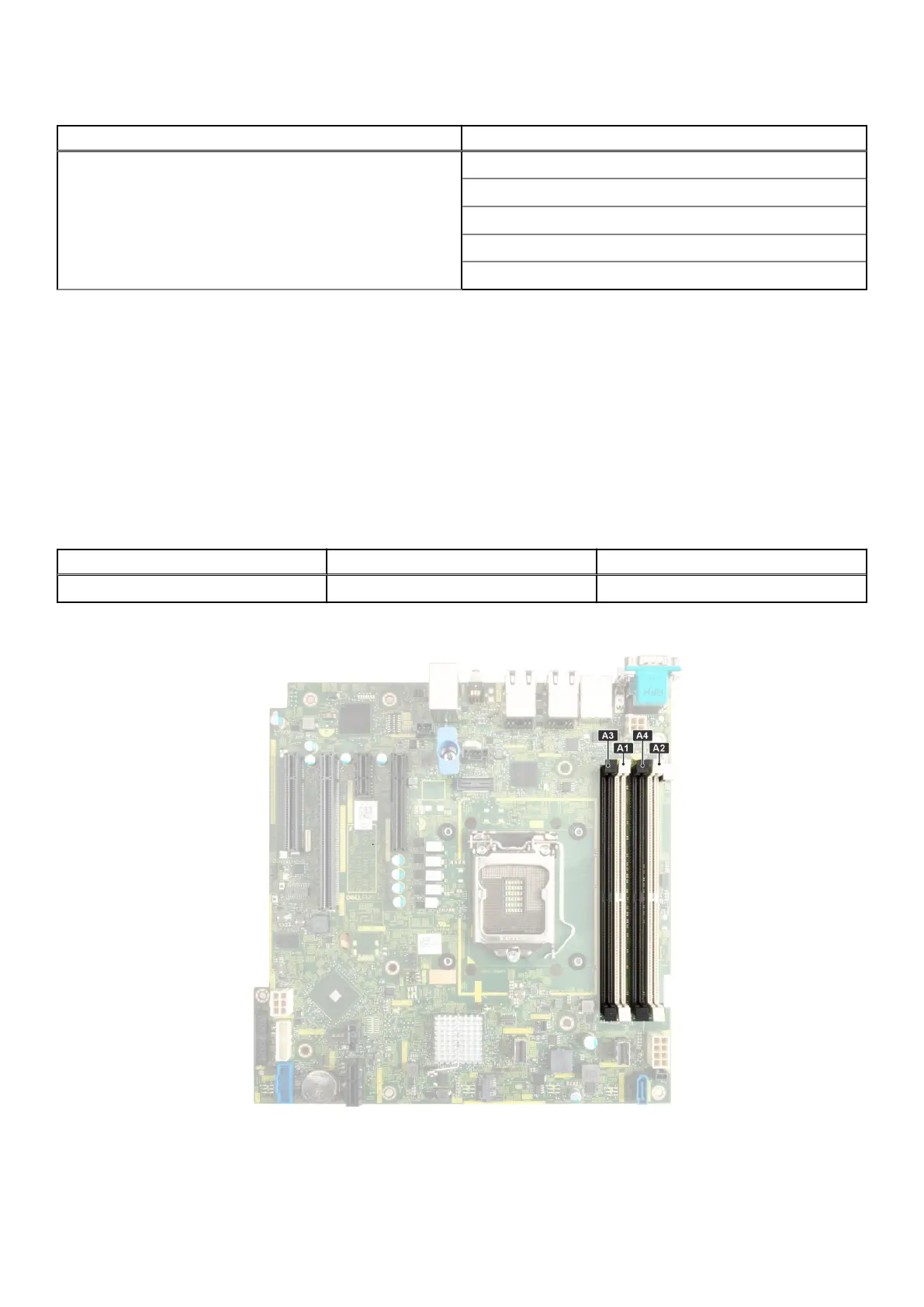
Your system contains four memory sockets. Two memory channels are allocated to the processor.
Memory channels are organized as follows:
Table 17. Memory channels
Processor Channel A Channel B
Processor 1 A1, A3 A2, A4
Figure 46. Memory socket location
Installing and removing system components
59
 Loading...