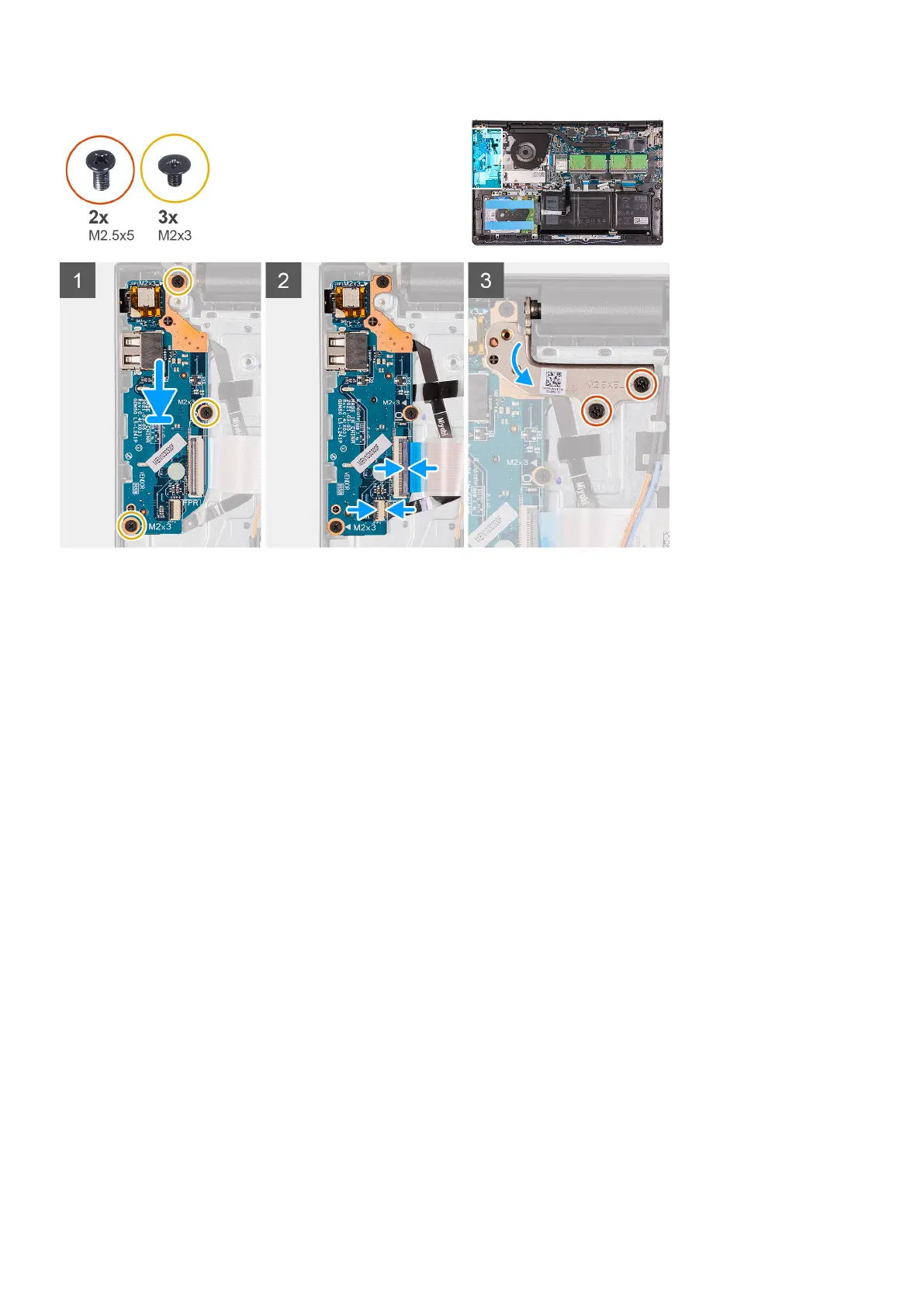
Steps
1. Align and place the I/O board under the left hinge assembly and on to the palm-rest and keyboard assembly.
2. Replace the three (M2x3) screws to secure the I/O daughter board to the palm-rest and keyboard assembly.
3. Connect the fingerprint-reader board cable to the connector on the I/O board and close the latch, if applicable.
4. Connect the I/O-board power cable to the connector on the I/O board and close the latch.
5. Fold back the left hinge over the I/O board.
6. Replace the two (M2.5x5) screws to secure the hinge to the palm-rest and keyboard assembly.
Next steps
1. Install the base cover.
2. Exit service mode.
3. Install the SD card.
4. Follow the procedure in after working inside your computer.
Touchpad
Removing the touchpad assembly
Prerequisites
1. Follow the procedure in before working inside your computer.
2. Remove the SD card.
3. Remove the base cover.
4. Remove the battery.
About this task
The following images indicate the location of the touchpad and provides a visual representation of the removal procedure.
Removing and installing components
45
 Loading...