System configurations - rear view for PowerEdge
XR4000r
Rear view of the system
Table 4. Rear view of the system
Item Ports, panels, or slots Icon Description
1 Blank Filler N/A Blank filler cover the AC-socket opening, when power supply cables
from the front of the chassis.
2 Kensington lock slot N/A Kensington lock slot for securing the chassis.
Power supply unit indicator codes
AC and DC power supply units (PSUs) have an illuminated translucent handle that serves as an indicator. The indicator shows if
power is present or if a power fault has occurred.
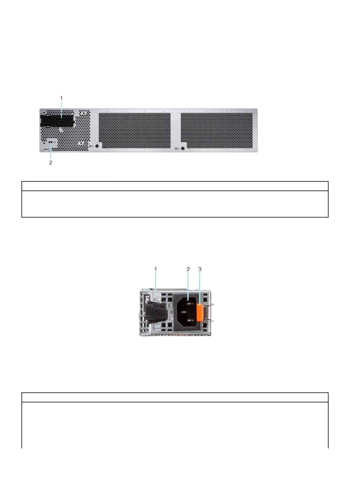
Figure 4. AC PSU status indicator
1. AC PSU handle
2. Socket
3. Release latch
Table 5. AC PSU status indicator codes
Power indicator codes Condition
Green Indicates that a valid power source is connected to the PSU
and the PSU is operational.
Blinking amber Indicates an issue with the PSU.
Not powered on Indicates that the power is not connected to the PSU.
Blinking green Indicates that the firmware of the PSU is being updated.
8 Dell PowerEdge XR4000r system configurations and features
 Loading...