Chapter 5 Analog Input/Output Module AS06XA
5- 21
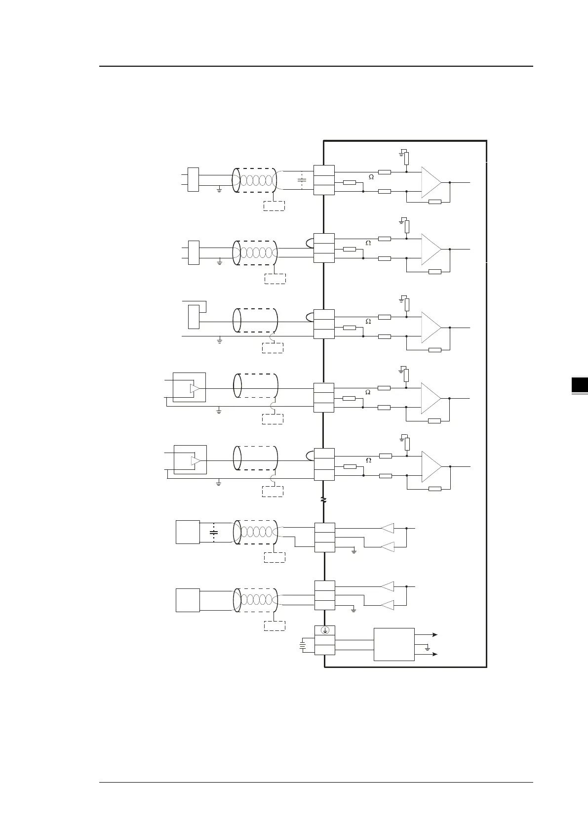
External wiring
(1) AS06XA-A
CH 1
1M
C H 2
1M
1 M
A G
1M
25 0
25 0
VO2
IO2
AG
0m A~2 0m A
C H 6
AG
VO1
IO1
AG
-10 V~+ 1 0V
*5
C H5
AG
24 VD C
D C /D C
+1 5V
*7
* 6
* 6
FE
FE
C H 3
1 M
A G
1M
25 0
-10 V~ +1 0V
V1 +
I1+
VI1 -
V 3+
I3 +
VI 3-
*3
*2
+
-
-20 mA~ + 20 mA
V 2+
I2 +
VI 2-
*2
+
-
+
-
+ 24 V
0 V
+2 4V
0V
4 mA ~+20 mA
* 6
FE
+ 24V
0V
V4 +
I 4+
V I4 -
C H4
1M
AG
1 M
2 50
C H1
1M
AG
1 M
2 50
-2 0m A~ +2 0m A
+ 2 4V
+
-
V 1+
I1 +
V I1 -
*2
-10 V~ +1 0V
+2 4V
+
-
*6
FE
*6
FE
0V
0V
FE
*6
FE
*6
0V
C HX - I
*8
CH X- I
* 8
C HX -I
*8
C HX -I
*8
C HX- O
*8
CH X- O
*8
Sh ielded cabl e *1
Sh ielded cabl e *1
Sh ielded cabl e *1
Sh ielded cabl e *1
4-w ire: cu rrent input
3-wir e: voltage in put
2-wire: cur rent input
3-w ire: cu rrent input
AC motor dr ive,
rec order,
proportioning v alv e
Current output
AC motor dr ive,
rec order,
proportioning v alv e
Vol tage o utput
Sh ielded cabl e *4
Sh ielded cabl e *4
AG
-15 V
AG
C HX -I
24 V
*8
Sh ielded cabl e *1
4-w ire: voltag e inp ut
C o nv ert er
*1. Use shielded cables to isolate the analog input signal cable from other power cables.
*2. If the module is connected to a current signal, the terminals Vn and In+ (n=1–4) must be short-circuited.
*3. If variability in the input voltage results in interference within the wiring, connect the module to a capacitor
having a capacitance between 0.1–0.47 μF and a working voltage of 25 V.
 Loading...