Chapter 11 DeviceNet Master Scanner Module AS01DNET-A
11-15
1
11.4.3 IO Mapping for AS01DNET in AS PLC
11.4.3.1. Data Mapping between Modules and AS PLC
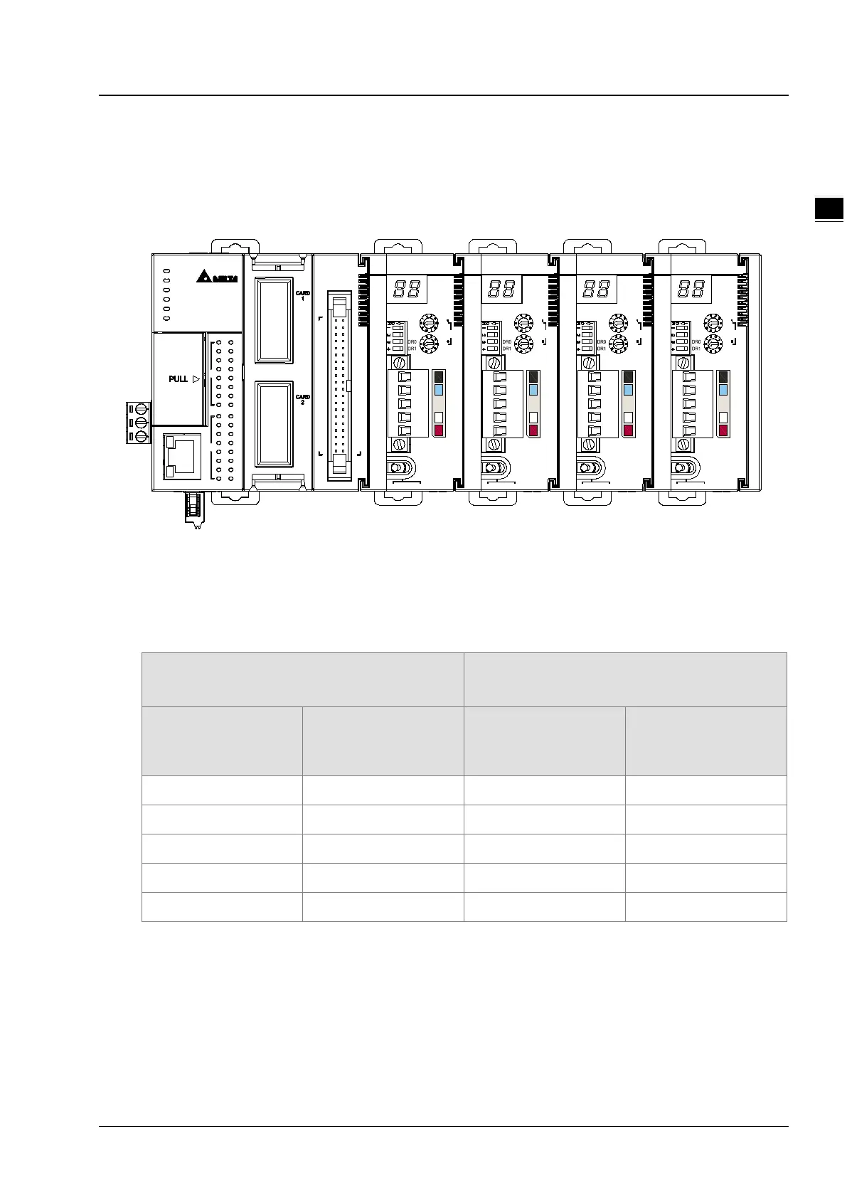
Up to four AS01DENT modules can be connected to the right side of AS PLC at most. After AS01DNET modules and
PLC are connected, PLC will assign data mapping areas to each module.
AS01DNET modules are connected to the right of the PLC. The position of the first module on the right of AS PLC is 1, the
second module is 2, the third module is 3 and the fourth module is 4. The position is only defined for network modules such
as AS01DNET and AS00SCM, instead of digital modules, analog modules, temperature modules, and weight-
measurement modules. The positions of AS01DNET modules on the right of the PLC are shown in the following table
where there are two arrangement ways of module connections.
Example 1 Example 2
Position of AS01DNET
on the right of the PLC
Arrangement order of
AS PLC and modules
on the right of the PLC
Position of AS01DNET
on the right of the PLC
Arrangement order of
AS PLC and modules
on the right of the PLC
AS PLC AS PLC
1 AS01DNET 1 AS01DNET
AS04AD AS04AD
2 AS01DNET AS00SCM
3 AS01DNET
01DNET
MS
NS
x10
x10
IN 0
IN 1
Node Address
RTU Master Slave
/
01DNET
MS
NS
x10
x10
IN 0
IN 1
Node Address
RTU Master Slave
/
01DNET
MS
NS
x10
x10
IN 0
IN 1
Node Address
RTU Master
Slave/
01DNET
MS
NS
x10
x10
IN 0
IN 1
Node Address
RTU Master Slave/
40
5
6
7
3
2
1
4
OUT
0
10
11
9
8
Ethernet
2
3
IN
4
6
5
7
1
0
10
11
9
8
COM1
AS324MT
COM2
BAT. L O W
POWER
RUN
ERROR
2 1
 Loading...