Chapter 11 DeviceNet Master Scanner Module AS01DNET-A
11-55
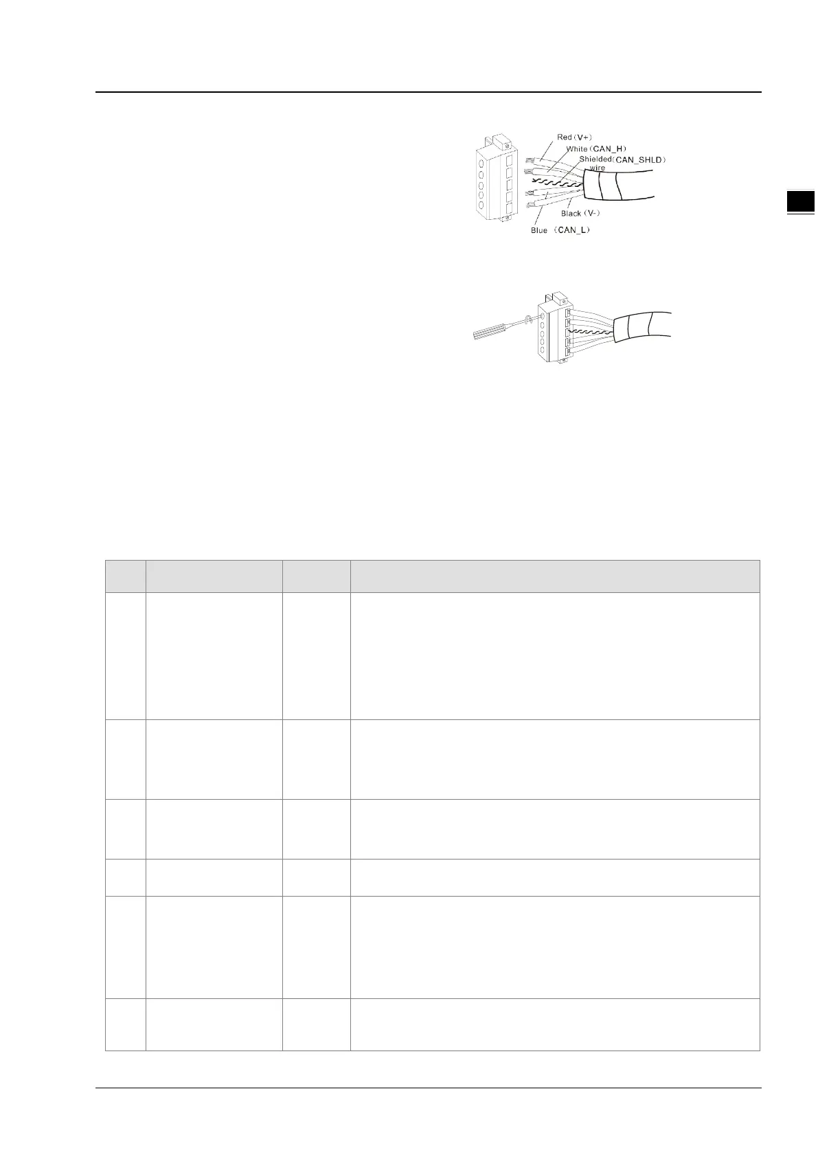
1
Insert the peeled communication cables into the
holes in the connector in correct order.
Tighten the screws on the connector by a slotted
screwdriver and fix the communication cables in the
holes in the connector.
11.5.4 Configuring AS01DNET (in RTU mode)
As DeviceNet slave, AS01DNET (RTU) mainly achieves the data exchange between the master and AS-series I/O modules
connected to AS01DNET.
Transmits output data of DeviceNet master to I/O modules.
Transmits input data from I/O modules to DeviceNet master.
11.5.4.1. Terms
No. Name Unit Description
1 Control word WORD
The first WORD for output data that the master assigns to AS01DNET is
the control word of AS01DNET for setting the work mode of AS01DNET.
When the content in the control word is set to 2, AS01DNET is in STOP
mode. When the content in the control word is set to 1, AS01DNET is in
RUN mode.
2 Status word WORD
The first WORD for input data that the master assigns to AS01DNET is
the status word of AS01DNET for displaying the operation state of
AS01DNET.
Refer to section 11.5.4.3.4 for more about status word.
5
Range of input data
in modules
WORD
Determined by start input address and input mapping parameter length
of each module.
6
Range of output data
WORD
Determined by start
output address and output mapping parameter
length of each module.
7 Input data size WORD
The sum of the size of status word of AS01DNET and the size of input
data of the modules connected to it. The status word occupies one word.
Digital input module takes 16 bits as one word. The input data length of
analog I/O modules and temperature modules are determined by the
default mapping parameter length and user-added parameter length, no
8 Output data size WORD
The sum of the size of control word of AS01DNET and the size of output
data of the modules connected to it. The control word occupies one word.
Digital output module takes 16 bits as one word. The output data length
 Loading...