Chapter 11 DeviceNet Master Scanner Module AS01DNET-A
11-5
1
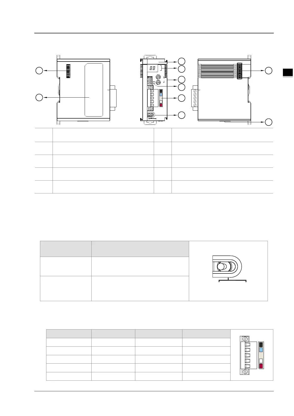
11.2.2 Components
①
Model name
⑥
Mode toggle
②
State indicators
⑦
Left-side extension port
③
Address switch
⑧
Nameplate
④
Function switch
⑨
Right-side extension port
⑤
DeviceNet communication port
⑩
24V DC power input port for RTU mode
Note:
The power input port of the network module is required to connect an external 24VDC power supply only when the toggle
(RTU- Master/Slave) is switched to RTU mode. Otherwise, the port does not need an external 24VDC power supply
connected when the toggle (RTU- Master/Slave) is switched to Master/Slave mode.
11.2.3 Mode Toggle(RTU- Master/Slave)
Mode Selection Description
Master/Slave
Works in master or slave mode and constitutes a
DeviceNet master or slave without external
power supply.
RTU
When working in remote (RTU) mode,
AS01DNET-A is required to connect
DC 24V power supply and can
have AS series
I/O modules connected on its right side.
11.2.4 DeviceNet Connector
The connector is used for the connection to DeviceNet. Wire by using the connector enclosed with AS01DNET –A.
Pin Signal Color Description
1 V- Black 0 VDC
2 CAN_L Blue Signal-
3 SHIELD - Shielded wire
4 CAN_H White Signal+
5 V+ Red 24 VDC
01DNET
MS
NS
x10
1
x10
0
IN 0
IN 1
Node Address
RTU Master Slave/
1
2
3
4
7
6
8
9
10
5
 Loading...