AS Series Module Manual
13-6
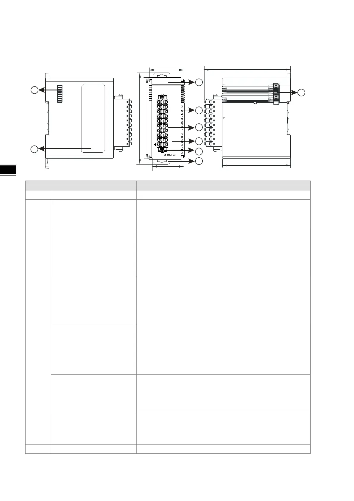
13.2.2
Profile
38.2 95
75
35
88
98.3
1
4
5
2
3
6
7
8
7
Q2
Q4
E4
Q3
E3
C4
E2
C3
CQ 1
Q1
E1
C2
MS
NS
C1
PW R
04 SI L
●
CQ2
L3+
L3
-
L4+
L4
-
DI 1
DI2
CQ3
DI3
CQ4
DI4
L2+
L2
-
L1+
L1
-
24 V
0V
Unit: mm
1 Model name Model name of the module
2
POWER LED indicator (Blue)
Indicates the status of the power supply
ON: the power is on
OFF: no power or the power voltage is too low
Module LED indicator
(Red)
Error status of the module
OFF: The module is normal.
ON: The communication with its left-side PLC or RTU module fails.
Blinking:
1. Module setting or communication error (blinks every 1 second)
2. Hardware or low voltage error (blinks every 0.2 second)
Network LED indicator
(Orange)
Error status of the network
ON: No external power supply
Blinking: Scanning is ongoing or the module is already configured and
the diagnosis is done.
OFF: The module has been configured but the diagnosis has not done
C1, C2, C3, C4 LED indicator
(Orange)
IO-Link connection status of each communication port
ON: The communication port is in IO-Link mode and a device is
connected.
Blinking: The communication port is in IO-Link mode but no device is
connected or the device connected is not configured.
OFF: The communication port is disabled or in SIO mode.
Q1, Q2, Q3, Q4 LED indicator
(Orange)
Indicates the status of input / output in SIO mode
ON: The input/output is working in SIO mode.
OFF: The communication port is disabled or in IO-Link mode.
E1, E2, E3, E4 LED indicator
(red)
Indicates if any warning or error occurs in each communication port of
the IO-Link connection.
Blinking: A warning or an error occurs
OFF: No warnings or errors
3 Removable terminal block IO-Link
 Loading...