ASDA-A2 Chapter 3 Wiring
Revision February, 2017 3-65
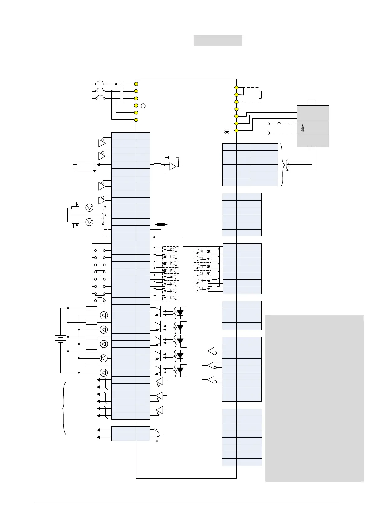
3.12 Standard Connection Example – 220V series
3.12.1 Position (PT) Control Mode
OCZ
GND
48
13
/HPULSE
HPULSE
SIGN
/PULSE
PULSE
/HSIGN
HSIGN
VDD
MON1
GND
MON2
COM+
COM-
DI1
DI2
DI3
DI4
DI5
DI6
DI7
DI8
DO1+
DO2-
DO3-
DO4-
DO2+
DO3+
DO4+
DO5+
DO1-
DO5-
/OA
OA
OB
/OB
/OZ
OZ
/SIGN
12,13,19
45,47,49
41
43
37
36
18
13
40
46
29
38
16
T-REF
GND
/SIGN
SIGN
15
17
11
9
10
34
8
33
32
30
7
6
5
4
3
1
2
26
28
31
21
22
24
50
27
25
23
RS485+
RS232_RX
RS232_TX
GND
RS485-
-
5
6
4
3
1
2
7
5
6
4
3
1
2
COM+
EDI9-
EDI10-
EDI11-
EDI12-
EDI13-
EDI14-
+5V DC
Data-
Data+
GND
4
3
1
2
1,9
3,11
2,10
4,12
5,13
6,14
7,15
8,16
CAN H
CAN L
CAN GND
-
-
-
CAN GND
-
Opt A
+5V
Opt B
Opt /B
Opt /A
Opt Z
Opt /Z
GND
GND
9
7
5
6
3
1
2
8
4
CN2
CN7
CN4
CN1
CN5
CN6 CANopen
P
⊕
D
C
U
V
W
4.7KΩ
4.7KΩ
4.7KΩ
4.7KΩ
4.7KΩ
4.7KΩ
4.7KΩ
4.7KΩ
4.7KΩ
4.7KΩ
4.7KΩ
4.7KΩ
4.7KΩ
4.7KΩ
Max. output
current 50mA
voltage 30V
R
S
T
L1c
L2c
MC
MCCB
Servo Drive
ASDA-A2 series
SON
CCLR
TCM0
TCM1
ARST
NL
PL
EMGS
1.5KΩ
1.5KΩ
1.5KΩ
1.5KΩ
1.5KΩ
SRDY
ZSPD
TPOS
HOME
ALRM
24V
A phase pulse
B phase pulse
Z phase pulse
Z phase open
collector
Encoder
Pulse
Output
10KΩ
10KΩ
Twisted-pair or
twisted-shield
cable
10KΩ
±10V
10KΩ
10KΩ
DC 24V
Regenerative
Resistor
Red
White
Black
Green
SG
Brake
Power Supply
Encoder
BRKREMGS
24V
AC 200/230 V
Three-phase
50/60Hz
*8
Pulse Input
(Line Driver)
*1
High-speed
Pulse Input
(Line Receiver)
*2
*3
*4
*5
*6
*7
T+
T-
-
+5V
-
GND
4
7
13,15
14,16
9
5
CN3
Blue
Blue/Black
-
Black/Black &
White
Red/Red &
White
-
SG
Twisted-pair or
twisted-shield
cable
Please note:
*1 Please refer to C3 ~ C4 wiring
diagrams in section 3.4.3.
*2 Please refer to C3 ~ C4 wiring
diagrams in section 3.4.3.
*3 Please refer to C9 ~ C12 wiring
diagrams (SINK / SOURCE mode)
in section 3.4.3.
*4 400W and below drives do not
provide built-in regenerative
resistor.
*5 The coil of brake has no polarity.
*6 For extension digital inputs (DI)
connections (CN7 is an optional
part, not Delta standard supplied
part.).
*7 For USB connection. It is used to
connect to personal computer or
notebook.
*8 Single -phase connections are for
servo drives 1.5kW and below only.
 Loading...


