EasyManua.ls Logo

Delta ECMA-E 1315 Series User Manual

Delta ECMA-E 1315 Series
721 pages
To Next Page IconTo Next Page
To Previous Page IconTo Previous Page
Page #121 background image
Chapter 3 Wiring ASDA-A2
3-74 Revision February, 2017
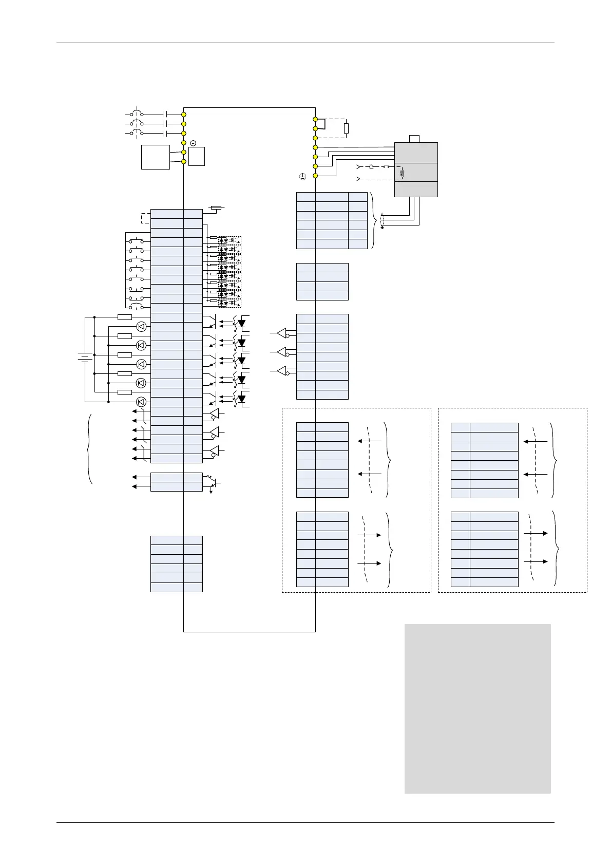
3.13.5 Communication Mode
VDD
COM+
COM-
DI1
DI2
DI3
DI4
DI5
DI6
DI7
DI8
DO1+
DO2-
DO3-
DO4-
DO2+
DO3+
DO4+
DO5+
DO1-
DO5-
45,47,49
17
11
9
10
34
8
33
32
30
7
6
5
4
3
1
2
26
28
31
27
T+
T-
-
+5V
-
GND
4
7
13,15
14,16
9
5
+5V DC
Data-
Data+
GND
4
3
1
2
Opt A
+5V
Opt B
Opt /B
Opt /A
Opt Z
Opt /Z
GND
GND
9
7
5
6
3
1
2
8
4
CN2
CN4
CN1
CN5
Blue
Blue/
Black
P
D
C
U
V
W
4.7KΩ
4.7KΩ
4.7KΩ
4.7KΩ
4.7KΩ
4.7KΩ
4.7KΩ
4.7KΩ
R
S
T
24V
0V
MC
MCCB
AC 380/480 V
3-phase
Servo Drive
ASDA-A2 series
Reserved
ORGP
NL
PL
EMGS
1.5KΩ
1.5KΩ
1.5KΩ
1.5KΩ
1.5KΩ
SRDY
ZSPD
TPOS
HOME
ALRM
24V
DC 24V
Regenerative
resistor
Red
White
Black
Green
SG
Brake
Power supply
Encoder
BRKREMGS
24V
Twisted-pair or
twisted-shield
cable
DC 24V
Power
Supply
Reserved
Reserved
Reserved
1
2
4
3
Red/Red&
White
Black/
Black&White
-
-
21
22
24
50
25
23
Max. output current 3A
Voltage 50V
CN3
CN6 DMCNET (
for ASDA-A2-F)
9
11
10
12
13
14
15
16
Data output
DMCNET_1A
-
-
-
-
DMCNET_1B
DMCNET_2A
DMCNET_2B
1
3
2
4
5
6
7
8
Data input
DMCNET_1A
-
-
-
-
DMCNET_1B
DMCNET_2A
DMCNET_2B
9
11
10
12
13
14
15
16
CAN H
CAN L
CAN GND
-
-
-
CAN GND
-
CN6 CANopen (
for ASDA-A2-M)
1
3
2
4
5
6
7
8
CAN H
CAN L
CAN GND
-
-
-
CAN GND
-
Data input
Data output
OCZ
GND
48
13
/OA
OA
OB
/OB
/OZ
OZ
A phase
differential signal
B phase
differential signal
Z phase
differential signal
Z phase signal
(open-collector)
Encoder
pulse
output
RS485+
RS232_RX
RS232_TX
GND
RS485-
-
5
6
4
3
1
2
Please note:
*1 Please refer to C9 ~ C12 wiring
diagrams (SINK / SOURCE
mode) in section 3.4.4.
*2 4.5kW and below drives provide
built-in regenerative resistor.
*3 The coil of brake has no
polarity.
*4 For USB connection. It is used
to connect to personal
computer or notebook.
*5 A2-F only supports DMCNET
mode.

Table of Contents

Questions and Answers:

Delta ECMA-E 1315 Series Specifications

General IconGeneral
BrandDelta
ModelECMA-E 1315 Series
CategoryServo Drives
LanguageEnglish

Summary

Chapter 1 Inspection and Model Explanation

1.1 Inspection

Instructions for inspecting the servo drive and motor to prevent damage during purchasing and delivery.

1.2 Product Model

Details on identifying and understanding the model names of ASDA-A2 series servo drives and ECMA series servo motors.

Chapter 2 Installation

Chapter 3 Wiring

Chapter 4 Panel Display and Operation

Chapter 5 Trial Operation and Tuning

5.1 Inspection without Load

Details the procedures for inspecting the servo motor and drive before operation, without applying power.

5.2 Applying Power to the Servo Drive

Provides instructions on correctly wiring and applying power to the servo drive, including voltage and wiring checks.

5.3 JOG Trial Run without Load

Explains how to perform a JOG trial run without load for testing motor and drive functionality.

5.6 Tuning Procedure

Covers the process of tuning the servo drive, including inertia estimation and various tuning methods.

Chapter 6 Control Mode of Operation

6.1 Selection of Operation Mode

Describes the available operation modes: Position, Speed, Torque, Dual, and Multi-modes.

Chapter 7 Motion Control

7.10 Parameter Settings

Details various parameters related to motion control, including target speed, acceleration/deceleration, and PR definitions.

Chapter 8 Parameters

8.1 Parameter Definition

Defines parameters, their grouping, communication addresses, and control modes.

8.2 List of Parameters

Provides a comprehensive list of parameters, including abbreviations, functions, defaults, and related sections.

8.3 Parameter Description

Details the function, default values, units, and related sections for various parameters.

Chapter 9 Communications

9.1 RS-485 & RS-232 Communication Hardware Interface

Explains the hardware interface for RS-485 and RS-232 communication, including configuration and wiring.

9.2 RS-485 / RS-232 Communication Parameters Setting

Details the essential parameters for servo drive communication, such as address, transmission speed, and protocol.

Chapter 10 Troubleshooting

10.1 Alarm of Servo Drive

Lists common servo drive alarms, their descriptions, corresponding DO signals, and servo status.

10.2 Alarm of CANopen Communication

Details CANopen communication alarms, their descriptions, corrective actions, and corresponding DO/Servo status.

10.3 Alarm of Motion Control

Lists alarms related to motion control, including causes, checking methods, and corrective actions.

10.4 Causes and Corrective Actions

Provides a table of common causes and corrective actions for servo drive alarms like Over current, Over voltage, etc.

10.5 Corrective Actions after the Alarm Occurs

Lists corrective actions for various alarms, suggesting steps like turning DI.ARST on or re-powering the servo drive.

Chapter 11 Specifications

11.1 Specifications of Servo Drives

Presents detailed specifications for ASDA-A2 series servo drives, including 220V and 400V series.

Chapter 12 Absolute System

12.1 Backup Battery Boxes

Covers safety precautions, specifications, dimensions, and connection cables for backup battery boxes.

12.3 System Initialization Procedure and Operation

Explains the system initialization process, including procedures for absolute system setup via digital I/O or parameters.

12.7 Alarms for Absolute System

Lists common alarms for absolute systems, including causes and corrective actions for encoder voltage, gray code, etc.

Appendix B Maintenance and Inspection

Inspection before operation

Checks to perform before applying power, including wiring, electrical conductivity, and control switch status.

Related product manuals