Home
Delta
Servo Drives
ECMA-E 1315 Series
Delta ECMA-E 1315 Series User Manual
4
of 1
of 1 rating
721 pages
Give review
Manual
Specs
To Next Page
To Next Page
To Previous Page
To Previous Page
Loading...
Chapter 3 Wiring
ASD
A-
A2
3-42
Revision February, 2017
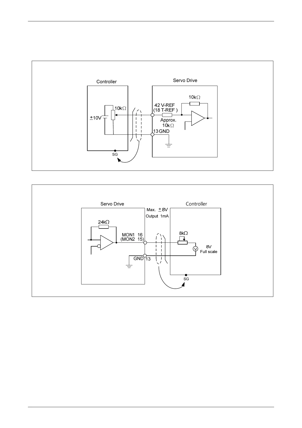
3.4.3 Wiring Diagrams (CN1)
The valid voltage of speed analog command and torque analog command is between -10V and
+10V. The command value can be set via relevant parameters. The input impedance is 10K
.
C1
: Speed, Input of Torque Analog Command
C2: Analog Monitor Output MON1 ,MON2
88
90
Table of Contents
default chapter
6
Table of Contents
6
Chapter 1 Inspection and Model Explanation
17
Product Model
18
Nameplate Information
18
Model Explanation
19
Servo Drive and Corresponding Servo Motor
21
Series
21
Series
23
Each Part of the Servo Drive
24
Series
24
Series
27
Chapter 2 Installation
30
Notes
30
Ambient Conditions of Storage
30
Ambient Conditions of Installation
30
Installation Direction and Space
31
Specification of Circuit Breaker and Fuse
34
EMI Filter Selection
35
Selection of Regenerative Resistor
38
Chapter 3 Wiring
48
Connections - 220V Series
48
Connecting to Peripheral Devices
48
Connectors and Terminals of Servo Drive
49
Wiring Method
51
Specification of Motor Power Cable
53
Specification of Encoder Cable Connector
55
Selection of Wiring Rod
59
Connections - 400V Series
61
Connecting to Peripheral Devices
61
Connectors and Terminals of the Servo Drive
63
Wiring Method
65
Specification of Motor Power Cable
66
Specification of Encoder Connector
68
Selection of Wiring Rod
70
Basic Wiring
72
Series
72
Series
75
I/O Signal (CN1) Connection
77
I/O Signal (CN1) Connector Terminal Layout
77
Signals Explanation of Connector CN1
79
Wiring Diagrams (CN1)
89
DI and DO Signal Specified by Users
97
Application: Using CN1 Quick Connector for Wiring
97
CN2 Connector
101
Wiring of CN3 Connector
104
Layout of CN3 Connector
104
Connection between PC and Connector CN3
105
CN4 Serial Connector (USB)
106
CN5 Connector (Full-Closed Loop)
107
CN6 Connector (Canopen)
108
Extension Digital Input Connector of CN7
110
CN8 Connector of Battery Box
111
Standard Connection Example - 220V Series
112
Position (PT) Control Mode
112
Position (PR) Control Mode
113
Speed Control Mode
114
Torque Control Mode
115
Communication Mode
116
Standard Connection Example - 400V Series
117
Position (PT) Control Mode
117
Position (PR) Control Mode
118
Speed Control Mode
119
Torque Control Mode
120
Communication Mode
121
Chapter 4 Panel Display and Operation
122
Panel Description
122
Parameter Setting Procedure
123
Status Display
126
Save Setting Display
126
Decimal Point
126
Alarm Message
126
Positive and Negative Sign Setting
126
Monitor Display
127
General Function
130
Operation of Fault Record Display
130
JOG Mode
131
Force DO Output
132
Digital Input Diagnosis Operation
133
Digital Output Diagnosis Operation
133
Chapter 5 Trial Operation and Tuning
134
Inspection Without Load
134
Applying Power to the Servo Drive
135
JOG Trial Run Without Load
139
Trial Run Without Load (Speed Mode)
140
Trial Run Without Load (Position Mode)
142
Tuning Procedure
144
Flowchart of Tuning Procedure
145
Inertia Estimation Flowchart (with Mechanism)
146
Flowchart of Auto Tuning
147
Flowchart of Semi-Auto Tuning
148
Limit of Inertia Ratio
149
Mechanical Resonance Suppression Method
151
Tuning Mode and Parameters
152
Tuning in Manual Mode
153
Chapter 6 Control Mode of Operation
156
Selection of Operation Mode
156
Position Mode
158
Position Command in PT Mode
158
Position Command in PR Mode
162
Control Structure of Position Mode
163
S-Curve Filter (Position)
164
Electronic Gear Ratio
167
Low-Pass Filter
170
Timing Diagram in Position Mode (PR)
171
Gain Adjustment of Position Loop
172
Low-Frequency Vibration Suppression in Position Mode
174
Speed Mode
179
Selection of Speed Mode
179
Control Structure of Speed Mode
180
Smooth Speed Command
181
The Scaling of Analog Command
185
Timing Diagram in Speed Mode
186
Gain Adjustment of Speed Loop
186
Resonance Suppression
193
Torque Mode
200
Selection of Torque Command
200
Control Structure of Torque Mode
201
Smooth Torque Command
202
The Scaling of Analog Command
202
Timing Diagram in Torque Mode
203
Dual Mode
204
Speed / Position Dual Mode
205
Speed / Torque Dual Mode
205
Torque / Position Dual Mode
206
Others
207
The Use of Speed Limit
207
The Use of Torque Limit
207
Analog Monitor
208
The Use of Brake
212
Chapter 7 Motion Control
214
Motion Control Functions of ASDA-A2
214
System Information
214
Description of Monitoring Variables
215
Description of Data Array
221
Description of Motion Axes
224
Description of PR Mode
225
The Difference between General PR Mode and the One in ASDA-A2
225
The Position Unit of PR Mode
226
Description of Register in PR Mode
226
Homing Description of PR Mode
228
DI/DO Provided by PR Mode and Diagrams
229
Parameter Settings
231
The Relation between the Previous Path and the Next Path
238
Programming the Path in PR Mode
239
The Description of E-Cam Function
240
Function Description of CAPTURE (Data Capture)
247
Function Description of COMPARE (Data Compare)
249
Chapter 8 Parameters
252
Parameter Definition
252
List of Parameters
253
Parameter Description
264
P0-XX Monitor Parameters
264
P1-XX Basic Parameters
291
P2-XX Extension Parameters
342
P3-XX Communication Parameters
387
P4-XX Diagnosis Parameters
398
P5-XX Motion Setting Parameters
412
P6-XX PR Parameters
476
P7-XX PR Parameters
518
Chapter 9 Communications
546
RS-232 Communication Hardware Interface
546
RS-232 Communication Parameters Setting
548
MODBUS Communication Protocol
551
Write-In and Read-Out Communication Parameters
563
Chapter 10 Troubleshooting
564
Alarm of Servo Drive
564
Alarm of Canopen Communication
568
Alarm of Motion Control
570
Causes and Corrective Actions
573
Corrective Actions after the Alarm Occurs
592
Chapter 11 Specifications
598
Specifications of Servo Drives
598
ASDA-A2 220V Series
598
ASDA-A2 400V Series
601
Specifications of Servo Motors (ECMA Series)
604
ECMA 220V Series
604
ECMA 400V Series
614
Torque Features (T-N Curves)
622
Series
622
Series
624
Overload Features
626
Dimensions of Servo Drive
628
Series
628
Series
635
Dimensions of Servo Motor (ECMA Series)
638
Series
638
Series
645
Chapter 12 Absolute System
650
Backup Battery Boxes
651
Specifications
651
Battery Box Dimensions
653
Connection Cables for Absolute Encoder
654
Battery Box Cords
656
Installation
657
Connection Examples
657
How to Install a Battery
661
How to Replace a Battery
662
System Initialization Procedure and Operation
664
System Initialization Procedure
664
Pulse Counting
665
PUU Counting
666
Use Digital Inputs/Outputs to Initialize an Absolute System
667
Use Parameters to Initialize an Absolute System
667
Use Digital Inputs/Outputs to Read the Absolute Coordinate Data
668
Use Parameter to Read the Absolute Coordinate Data
672
Related Parameters for Absolute System
673
Digital Input (DI) Function Definition (for Absolute System)
679
Digital Output (DO) Function Definition (for Absolute System)
680
Alarms for Absolute System
681
Causes and Corrective Actions
682
Related Monitoring Variables
684
Appendix A Accessories
686
Appendix B Maintenance and Inspection
721
4
Based on 1 rating
Ask a question
Give review
Questions and Answers:
Need help?
Do you have a question about the Delta ECMA-E 1315 Series and is the answer not in the manual?
Ask a question
Delta ECMA-E 1315 Series Specifications
General
Brand
Delta
Model
ECMA-E 1315 Series
Category
Servo Drives
Language
English
Related product manuals
Delta ECMA-C 0807 Series
721 pages
Delta ASDA A2-E
129 pages
Delta ASDA Series
274 pages
Delta VFD220VL43C-J
235 pages
Delta VFD450VL43C-J
235 pages
Delta ASD-A2 Series
721 pages
Delta VFD300VL43C-J
235 pages
Delta VFD550VL43C-J
235 pages
Delta VFD-VJ Series
235 pages
Delta ASDA-A2 Series
721 pages
Delta ASDA-B2 Series
345 pages
Delta ASDA-B2-F Series
291 pages
 Loading...


