Chapter 3 Wiring ASDA-A2
3-2 Revision February, 2017
NOTE
Installation notes:
1. Check if the power and wiring among R, S, T and L1c, L2c are correct.
Please refer to Chapter 11 for Specifications. Make sure the input voltage
is correct, or it might damage the servo drive or danger may occur.
2. Please check if the output terminal U, V, W of the servo motor is correctly
wired. The incorrect wiring may disable the operation of the motor or cause
malfunction.
3. When applying to the external regenerative resistor, the contact between P
and D should be opened and the external regenerative resistor should
connect to terminal P and C. When applying to the internal regenerative
resistor, the contact between P and D should be closed and the contact
between P and C should be opened.
4. When an alarm occurs or the system is in emergency stop status, use
ALARM or WARN to output and disconnect the power of magnetic
contactor in order to disconnect the power of servo drive.
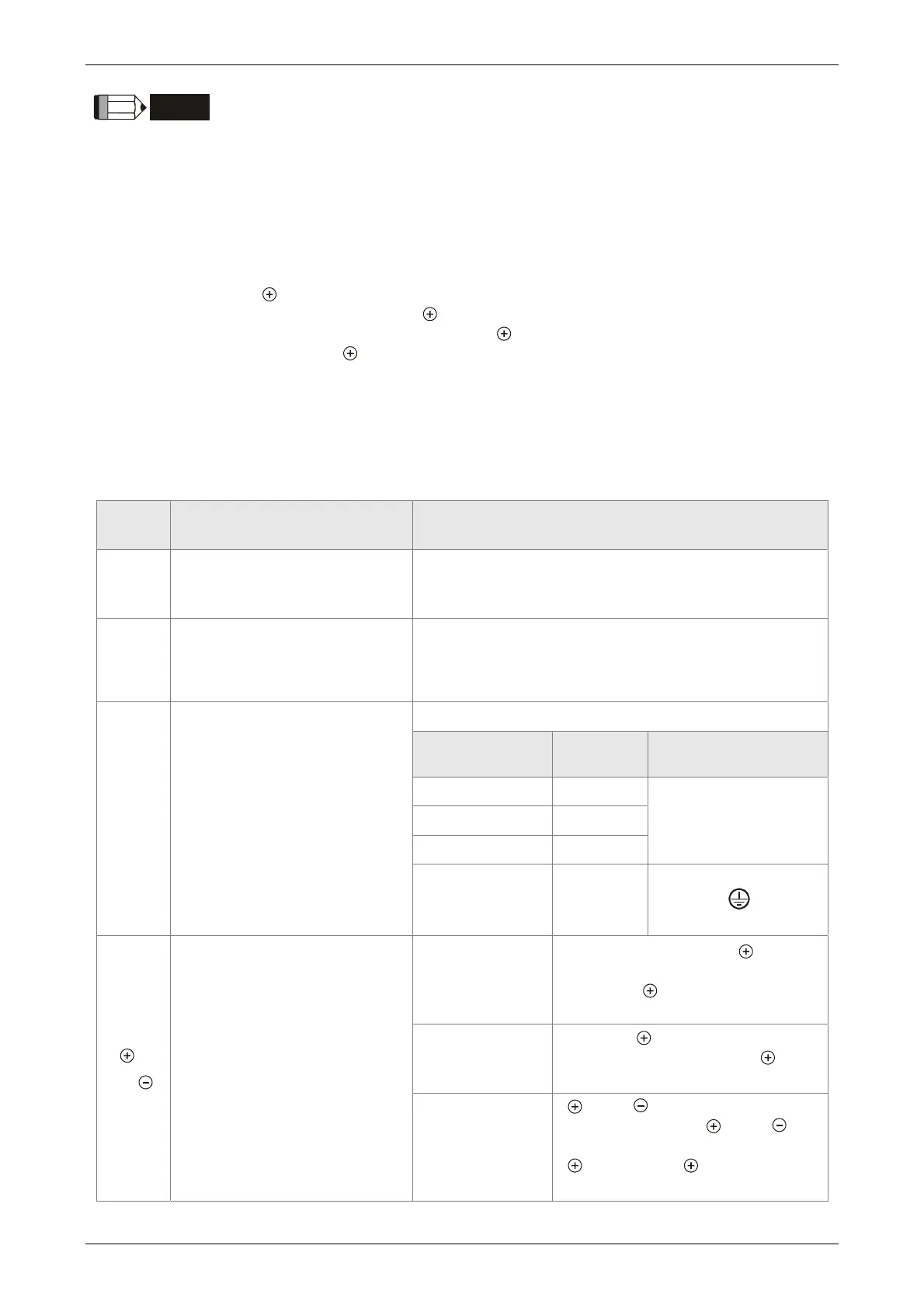
3.1.2 Connectors and Terminals of Servo Drive
Terminal
Signal
Name Description
L1c, L2c
Power input of the control
circuit
Connect to single-phase AC power (select the
appropriate voltage specification according to the
product )
R, S, T
Power input of the main
circuit
Connect to three-phase AC power (select the
appropriate voltage specification according to the
product)
U, V, W
FG
Motor cable
Connect to the servo motor
Terminal
Symbol
Wire Color Description
U Red
Three-phase main
power cable of the
motor.
V White
W Black
FG Green
Connect to ground
terminal (
) of the
servo drive.
P, D,
C,
Regenerative resistor
terminal or braking unit
Internal resistor
The contact between P and D
end should be closed; contact
between P and C end should
be opened.
External resistor
Connect P , C ends to the resistor
and the contact between P and D
end should be opened.
External braking
unit
P and P of the brake unit
should connect to P and P
respectively. The contact between
P and D and P and C should
be opened.
 Loading...


