Chapter 3 Wiring ASDA-A2
3-16 Revision February, 2017
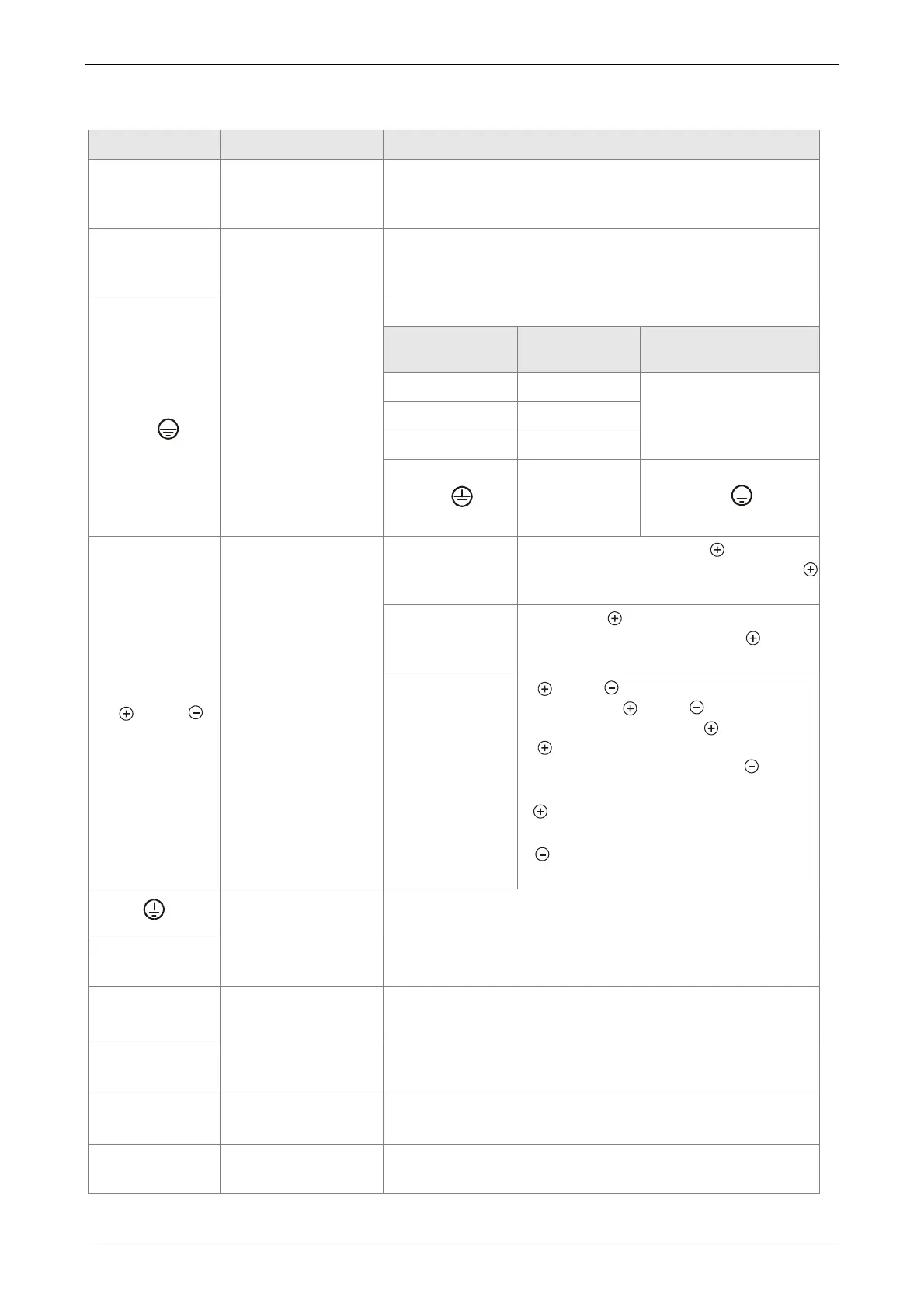
3.2.2 Connectors and Terminals of the Servo Drive
Terminal Signal Name Description
DC24V, DC0V
Power input of the
control circuit
Connect to single-phase AC power (select the
appropriate voltage specification according to the
product )
R, S, T
Power input of the
main circuit
Connect to three-phase AC power (select the
appropriate voltage specification according to the
product)
U, V, W
FG (
)
Motor cable
Connect to servo motor
Terminal
Symbol
Wire Color Description
U Red
Three-phase main
power cable of the
motor
V White
W Black
FG( )
Green
Connect to the
grounding
of the
servo drive.
P , D, C,
Regenerative
resistor terminal or
braking unit
Internal resistor
The contact between P and D end
should be closed; contact between P
and C end should be opened.
External
resistor
Connect P , C ends to the resistor
and the contact between P and D
end should be opened.
External
braking unit
P and P of the brake unit should
connect to P and P respectively.
The contact between P and D and
P and C should be opened. (N
terminal is built in L1C, L2C, and
R, S, T.)
P : Connect (+) terminal of V_BUS
voltage.
:
Connect to (-) terminal of
V_BUS voltage.
Ground terminal
Connect to the ground wire of the power and the servo
motor.
CN1
I/O connector
(Option)
Connect to the host controller, please refer to Section
3.4.
CN2
Connector (Option)
Connect to the encoder of the motor, please refer to
Section 3.5.
CN3
Connector (Option)
Connect to RS-485 or RS-232, please refer to Section
3.6
CN4
USB connector
(Type B) (Option)
Connect to personal computer (PC or NOTEBOOK),
please refer to Section 3.7
CN5
Connector (Option)
Connect to linear scale or encoder for full-closed loop
and motor feedback. Please refer to Section 3.8.
 Loading...


