 Loading...
Do you have a question about the Delta VFD17AME43AFNAA and is the answer not in the manual?
| Input Phase | 3-Phase |
|---|---|
| Enclosure | IP20 |
| Control Method | V/F Control, Sensorless Vector Control |
| Protection Features | Overcurrent, Overvoltage, Overheat, Short circuit |
| Communication Interface | RS-485 |
| Cooling Method | Fan Cooled |
| Operating Temperature | -10°C to 50°C |
| Storage Temperature | -20°C to 60°C |
| Altitude | 1000 m (Derating required above 1000 m) |
Details about the drive's nameplate markings, including model, input/output voltage, frequency range, and certifications.
Explanation of the model name structure and its components, specifying version type, safety function, and protection level.
Explanation of the serial number format, indicating production week, year, factory, and model number.
Instructions on how to use the service link label and QR code to apply for after-sales service via mobile device.
Information on the RFI jumper's function, its effect on EMC filter performance, and how to remove it.
Detailed dimensions (W, H, D, W1, H1, D1, S1) for Frame A models, including mounting hole specifications.
Detailed dimensions (W, H, D, W1, H1, D1, S1) for Frame B models, including mounting hole specifications.
Detailed dimensions (W, H, D, W1, H1, D1, S1) for Frame C models, including mounting hole specifications.
Detailed dimensions (W, H, D, W1, H1, D1, S1) for Frame D models, including mounting hole specifications.
Safety precautions and minimum mounting clearances required for installation to ensure proper heat dissipation and fan operation.
Diagram illustrating the system wiring, including power input, NFB, contactor, reactors, EMC filter, and motor connections.
Detailed explanation and precautions for wiring the AC motor drive, covering power input and control terminals.
Diagram showing the main circuit connections, including terminals for power input, DC reactor, brake resistor, and motor.
Specifications and dimensions of ring lugs used for main circuit terminal wiring, including wire size recommendations.
Precautions for analog input signals, including shielded wiring, twisted-pair wire, and use of capacitors/ferrite cores.
Explanation of contact input terminals, including Sink and Source modes and their switch connections.
Precautions for connecting digital outputs to the correct polarity and wiring specifications for control terminals.
Table detailing applicable motor models, braking torque, resistor specifications, and current ratings for brake units.
Guidance on selecting non-fuse circuit breakers based on UL standards and the drive's maximum rated input current.
Chart listing fuse specifications required for branch circuit protection in the United States and Canada.
Information on AC input reactors for improving power factor, reducing current, and suppressing surges.
Details on two types of zero phase reactors for suppressing interference at the main input or motor output.
Guidance on choosing optional EMC filters to enhance EMC capability and reduce problems caused by EMC.
Description of EMC shield plates (MKM-EPA, MKM-EPB, MKM-EPC, MKM-EPD) for use with shielded cables.
Installation diagram and specifications for the capacitive filter (CXY101-43A) used for basic filtering and noise reduction.
Details on conduit boxes compliant with NEMA 1 / UL Type 1 protection levels, including dimensions for different frames.
Information on fan kits (MKM-FKMA, MKM-FKMB, MKM-FKMC, MKM-FKMD) and instructions for fan removal.
Instructions and torque values for DIN-rail mounting adapters (MKM-DRB, MKM-DRC) for different frames.
Details on mounting adapter accessories (MKM-MAPB, MKM-MAPC) for changing wiring methods and flexible installation.
Introduction to digital keypads, including their panel layout, communication interface, and installation methods.
Step-by-step instructions for installing option cards, including removing the front cover and fastening screws.
Product profile, features, and specifications for the EMM-SAF01 STO card, detailing its safe torque off function.
Detailed specifications for the 115V series, one-phase models, including output rating, input rating, weight, and cooling method.
Detailed specifications for the 230V series, covering both one-phase and three-phase models.
Detailed specifications for the 460V series, three-phase models, including output rating, input rating, and EMC filter options.
Overview of general specifications, control characteristics, application macros, protection features, and certifications.
Environmental conditions for operation, storage, and transportation, including temperature, humidity, air pressure, and vibration resistance.
Guidelines for derating output current based on ambient temperature and altitude to ensure optimal performance.
Overview of the digital keypad layout, including the main display area, status display, and selection keys.
Explanation of the functions associated with each key on the keypad, including RUN, STOP/RESET, FWD/REV, ENTER, and ESC.
Step-by-step guides for operating the keypad, covering main page selection, frequency setting, and application selection.
Summary of drive parameters, including identity code, rated current, parameter reset, start-up display, and multi-function display settings.
Overview of basic parameters related to motor operation frequency, voltage, and acceleration/deceleration times.
Details on digital input/output parameters, including operation control modes and multi-function input/output terminal settings.
Information on analog input/output parameters, covering selection, bias, gain, filter time, and signal loss settings.
Parameters for setting multi-step speeds, including frequency settings for each step and related timing diagrams.
Parameters for configuring motor settings, including auto-tuning, full-load current, rated power, speed, and poles.
Overview of protection parameters, including low voltage, over-voltage, and over-current stall prevention settings.
Details on special parameters such as software brake, DC brake, fan cooling, and energy-saving functions.
Parameters for advanced PID control, including terminal selection, gains, time settings, and compensation modes.
Parameters for communication settings, including address, transmission speed, fault treatment, and protocol selection.
Parameters for speed feedback control, including pulse input type, frequency deviation, and PM FOC sensorless settings.
Parameters for advanced system control, including PWM mode selection and system control flags.
Parameters for various functions, including set point deviation, liquid leakage detection, and multi-pump control.
Parameters for application selection and user-defined macro settings, including defaults for fan, pump, conveyor, and packing.
Parameters for protection functions, covering output frequency, voltage, current, and IGBT temperature at malfunction.
Details on drive parameters like identity code, rated current, parameter reset, and start-up display settings.
Basic parameter settings for motor operation, including frequency, voltage, and mid-point settings.
Description of digital input/output parameters, covering operation control modes and multi-function terminal settings.
Details on analog input/output parameters, including selection, bias, gain, filter time, and signal loss settings.
Parameters for multi-step speed control, including frequency settings for each step and timing diagrams.
Parameters for configuring motor characteristics, including auto-tuning, current, power, speed, and poles.
Protection parameters like low voltage, over-voltage, and over-current stall prevention.
Parameters for special functions like software brake, DC brake, fan cooling, and energy-saving settings.
Parameters for advanced PID control, covering terminal selection, gains, time settings, and compensation.
Parameters for communication settings, including address, speed, fault treatment, and protocol.
Parameters for speed feedback control, including pulse input type, frequency deviation, and estimator settings.
Parameters for advanced system control, including PWM mode selection and system control flags.
Parameters for various functions like set point deviation, liquid leakage detection, and multi-pump control.
Application selection macros and user-defined parameter settings for fan, pump, conveyor, and packing.
Protection parameters covering output frequency, voltage, current, and IGBT temperature at malfunction.
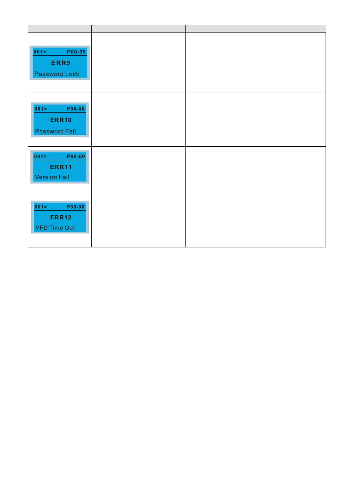
List of warning codes displayed on the LCM keypad, including warning names, descriptions, and corrective actions.
Description of OC fault, action and reset procedures, causes, and corrective actions for over-current during acceleration.
Description of OCD fault, action and reset procedures, causes, and corrective actions for over-current during deceleration.
Description of OCN fault, action and reset procedures, causes, and corrective actions for over-current during steady operation.
Description of GFF fault, action and reset procedures, causes, and corrective actions for ground faults.
Description of OCS fault, action and reset procedures, causes, and corrective actions for over-current at stop.
Description of OVA fault, action and reset procedures, causes, and corrective actions for over-voltage during acceleration.
Description of OVD fault, action and reset procedures, causes, and corrective actions for over-voltage during deceleration.
Description of OVN fault, action and reset procedures, causes, and corrective actions for over-voltage at constant speed.
Description of OVS fault, action and reset procedures, causes, and corrective actions for over-voltage at stop.
Description of LVA fault, action and reset procedures, causes, and corrective actions for low-voltage during acceleration.
Description of LVD fault, action and reset procedures, causes, and corrective actions for low-voltage during deceleration.
Description of LVN fault, action and reset procedures, causes, and corrective actions for low-voltage during constant speed.
Description of LVS fault, action and reset procedures, causes, and corrective actions for low-voltage at stop.
Description of ORP fault, action and reset procedures, causes, and corrective actions for phase loss protection.
Description of OH1 fault, action and reset procedures, causes, and corrective actions for IGBT overheating.
Description of tH1o fault, action and reset procedures, causes, and corrective actions for IGBT temperature detection failure.
Description of OL fault, action and reset procedures, causes, and corrective actions for overload.
Description of EOL1 fault, action and reset procedures, causes, and corrective actions for electronic thermal relay 1 protection.
Description of EOL2 fault, action and reset procedures, causes, and corrective actions for electronic thermal relay 2 protection.
Description of OH3 fault, action and reset procedures, causes, and corrective actions for motor overheating (PTC).
Description of OT1 fault, action and reset procedures, causes, and corrective actions for over-torque 1.
Description of OT2 fault, action and reset procedures, causes, and corrective actions for over-torque 2.
Description of UC fault, action and reset procedures, causes, and corrective actions for under current.
Description of CF2 fault, action and reset procedures, causes, and corrective actions for EEPROM read error.
Description of CD1 fault, action and reset procedures, causes, and corrective actions for U-phase current detection error.
Description of CD2 fault, action and reset procedures, causes, and corrective actions for V-phase current detection error.
Description of CD3 fault, action and reset procedures, causes, and corrective actions for W-phase current detection error.
Description of HD0 fault, action and reset procedures, causes, and corrective actions for current clamp hardware protection error.
Description of HD1 fault, action and reset procedures, causes, and corrective actions for over-current hardware protection error.
Description of AUE fault, action and reset procedures, causes, and corrective actions for motor auto-tuning error.
Description of the STO function, its dual-channel inputs (S1, S2), and compliance with international safety standards.
Detailed description of STO related terminal functions, signal inputs, and action logic for S1/S2 signal input.
Internal circuit diagram for the safe control loop, including wiring details for STO mode and ESTOP contact switch.
Table listing relevant safe loop parameters such as SFF, HFT, SIL, PFH, PFDav, PTI, Category, PL, MTTFd, and DC.
Instructions on how to use Pr.06-44 to specify the reset method when an STO alarm occurs.
Timing diagrams illustrating signal status under different conditions for normal operation and STO/STL1/STL2 modes.
Description of STO error codes (76, 72, 77, 78) and troubleshooting instructions for related keypad displays.
Step-by-step verification of STO and related detection functions, including voltage checks and response times.