Chapter 12 Description of Parameter SettingsME300
12.1-06-20
Setting 2:
The protection method and action are the same as setting it to 0, but this disables the
current limit when output current is the derating ratio ×120% (default value) in normal duty and is
the derating ratio ×180% (default value) in heavy duty.
The advantage is that this can provide a higher starting output current when the carrier
frequency setting is higher than the default. The disadvantage is that the carrier wave derates
easily when it overloads.
Example:
When Pr.06-55 = 0 or 1, over-current stall prevention level = ratio * Pr.06-03.
When Pr.06-55 = 2, the over-current stall prevention level = Pr.06-03. Use with the settings
for Pr.00-16 and Pr.00-17.
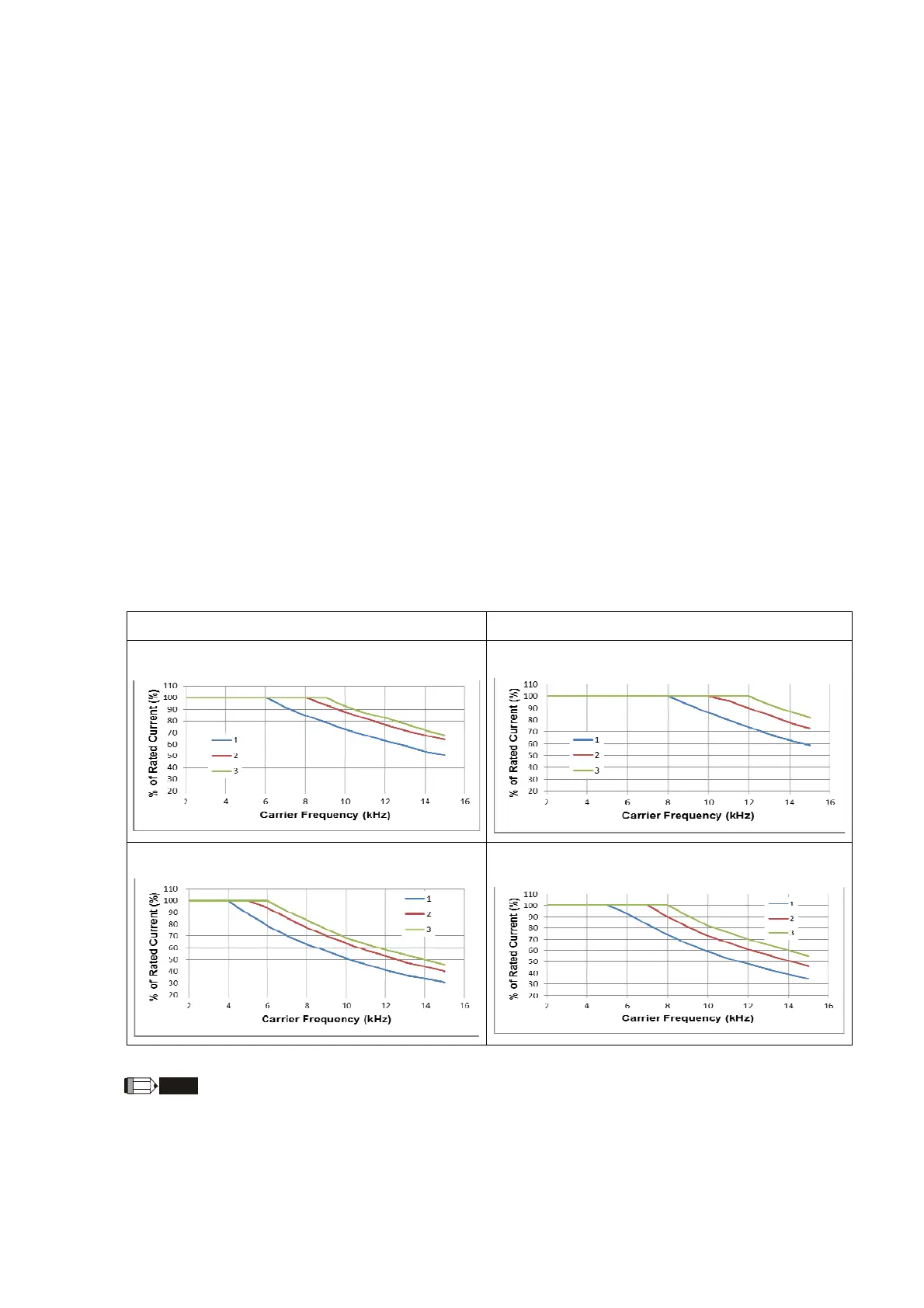
The ambient temperature also affects the derating; refer to ambient temperature derating curve.
Example:
Take VFD9A0ME43ANSAA in normal duty for example: ambient temperature 50ºC, UL
open-type, and independent installation. When the carrier frequency is set to 10 kHz, it
corresponds to 75% of the rated output current. The ambient temperature 60ºC corresponds to
75% * 75% of the rated output current.
You can adjust the derating curve modulation mode (when Pr.00-10=0 and Pr.00-11=0–3)
with Pr.11-41.
In normal duty mode (Pr.00-16 = 0) In heavy duty mode (Pr.00-16 = 1)
Normal duty / two-phase modulation mode
Heavy duty / two-phase modulation mode
Normal duty / space vector modulation mode
Heavy duty / space vector modulation mode
NOTE
Line 1: T
a
= 50
o
C / Duty = 100%
Line 2: T
a
= 50
o
C / Duty = 75% or T
a
= 40
o
C / Duty = 100%
Line 3: T
a
= 50
o
C / Duty = 50% or T
a
= 35
o
C / Duty = 100%
Ambient temperature derating curve for general control
 Loading...