106
EN5339QI (DIGITAL : IC17)
EX3AV Terminal Functions
06903 March 30, 2012 Rev: A
EN5339QI
Enpirion 2012 all rights reserved, E&OE www.enpirion.com, Page 2
EN5339QI EN5339 -40 to +85 24-pin (4mm x 6mm x 1.1mm) QFN T&R
EN5339QI-E EN5339 QFN Evaluation Board
Packing and Marking Information: http://www.enpirion.com/resource-center-packing-and-marking-information.htm
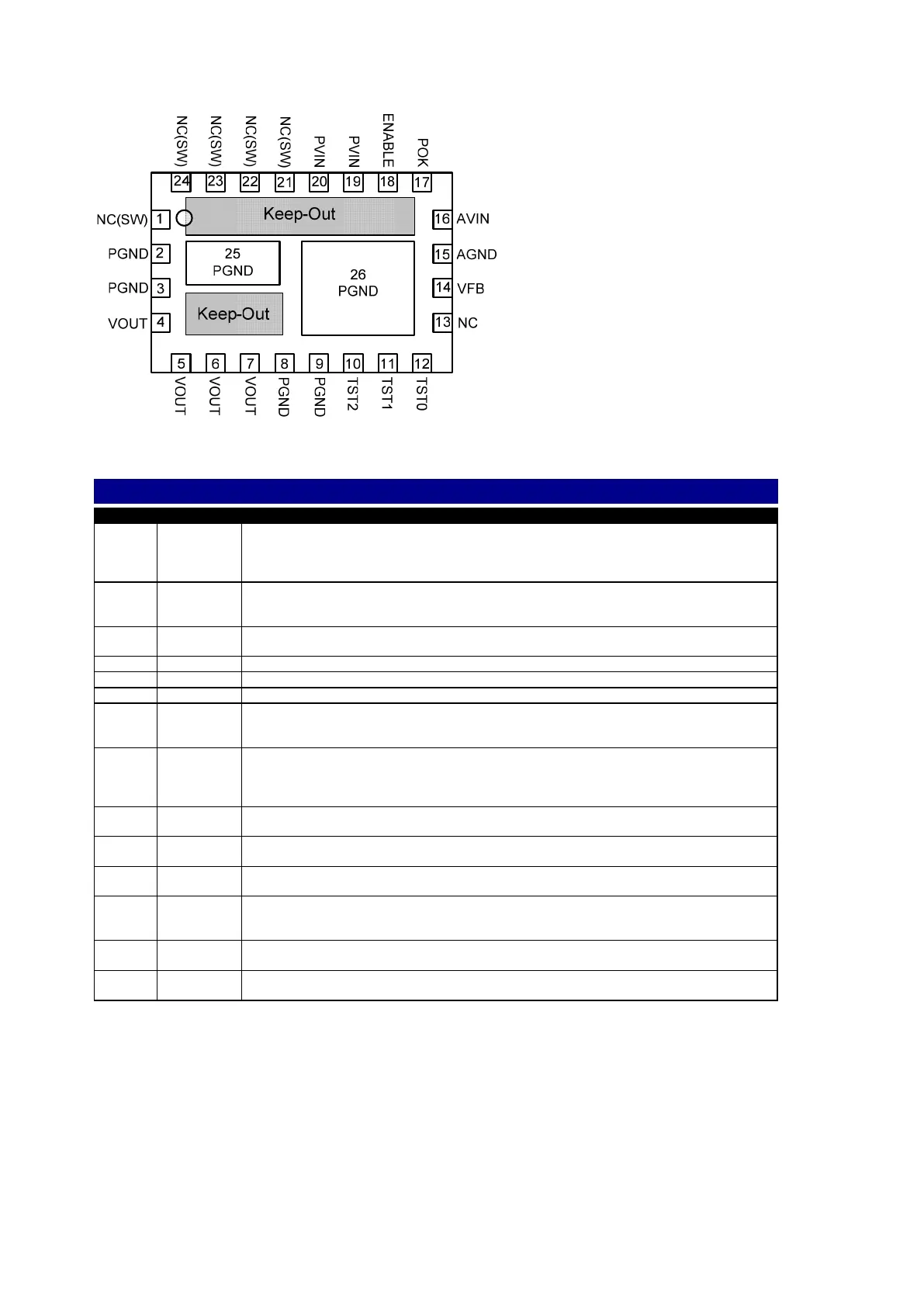
Figure 3: Pin Out Diagram (Top View)
NOTE A: NC pins are not to be electrically connected to each other or to any external signal, ground, or voltage.
However, they must be soldered to the PCB. Failure to follow this guideline may result in part malfunction or damage.
NOTE B: Grey area highlights exposed metal on the bottom of the package that is not to be mechanically or electrically
connected to the PCB. There should be no traces on PCB top layer under these keep out areas.
NOTE C: White ‘dot’ on top left is pin 1 indicator on top of the device package.
1, 21-24 NC(SW)
NO CONNECT: These pins are internally connected to the common switching node of the
internal MOSFETs. They must be soldered to PCB but not be electrically connected to any
external signal, ground, or voltage. Failure to follow this guideline may result in device
damage.
2-3, 8-9 PGND
Input and output power ground. Connect these pins to the ground electrode of the input and
output filter capacitors. See VOUT, PVIN descriptions and Layout Recommendation for more
details.
4-7 VOUT
Regulated converter output. Connect to the load and place output filter capacitor(s) between
these pins and PGND pins 7 and 8. See layout recommendation for details
10 TST2 Test Pin. For Enpirion internal use only. Connect to AVIN at all times.
11 TST1 Test Pin. For Enpirion internal use only. Connect to AVIN at all times.
06903 March 30, 2012 Rev: A
EN5339QI
Enpirion 2012 all rights reserved, E&OE www.enpirion.com, Page 2
EN5339QI EN5339 -40 to +85 24-pin (4mm x 6mm x 1.1mm) QFN T&R
EN5339QI-E EN5339 QFN Evaluation Board
Packing and Marking Information: http://www.enpirion.com/resource-center-packing-and-marking-information.htm
Figure 3: Pin Out Diagram (Top View)
NOTE A: NC pins are not to be electrically connected to each other or to any external signal, ground, or voltage.
However, they must be soldered to the PCB. Failure to follow this guideline may result in part malfunction or damage.
NOTE B: Grey area highlights exposed metal on the bottom of the package that is not to be mechanically or electrically
connected to the PCB. There should be no traces on PCB top layer under these keep out areas.
NOTE C: White ‘dot’ on top left is pin 1 indicator on top of the device package.
1, 21-24 NC(SW)
NO CONNECT: These pins are internally connected to the common switching node of the
internal MOSFETs. They must be soldered to PCB but not be electrically connected to any
external signal, ground, or voltage. Failure to follow this guideline may result in device
damage.
2-3, 8-9 PGND
Input and output power ground. Connect these pins to the ground electrode of the input and
output filter capacitors. See VOUT, PVIN descriptions and Layout Recommendation for more
details.
4-7 VOUT
Regulated converter output. Connect to the load and place output filter capacitor(s) between
these pins and PGND pins 7 and 8. See layout recommendation for details
10 TST2 Test Pin. For Enpirion internal use only. Connect to AVIN at all times.
11 TST1 Test Pin. For Enpirion internal use only. Connect to AVIN at all times.
06903 March 30, 2012 Rev: A
EN5339QI
Enpirion 2012 all rights reserved, E&OE www.enpirion.com, Page 3
12 TST0 Test Pin. For Enpirion internal use only. Connect to AVIN at all times.
13 NC
NO CONNECT: This pin must be soldered to PCB but not electrically connected to any other
pin or to any external signal, voltage, or ground. This pin may be connected internally. Failure
to follow this guideline may result in device damage.
14 VFB
This is the external feedback input pin. A resistor divider connects from the output to AGND.
The mid-point of the resistor divider is connected to VFB. A feed-forward capacitor is
required parallel to the upper feedback resistor (R
A
). The output voltage regulation is based
on the VFB node voltage equal to 0.600V.
15 AGND
The quiet ground for the control circuits. Connect to the ground plane with a via right next to
the pin.
16 AVIN
Analog input voltage for the control circuits. Connect this pin to the input power supply (PVIN)
at a quiet point. Decouple with a 1uF capacitor to AGND.
17 POK
POK is an open drain output. Refer to Power OK section for details. Leave POK open if
unused.
18 ENABLE
Output Enable. A logic high level on this pin enables the output and initiates a soft-start. A
logic low signal disables the output and discharges the output to GND. This pin must not be
left floating.
19-20 PVIN
Input power supply. Connect to input power supply and place input filter capacitor(s) between
these pins and PGND pins 2 to 3.
25,26 PGND
Not a perimeter pin. Device thermal pad to be connected to the system GND plane for heat-
sinking purposes. See Layout Recommendation section.
 Loading...