59
SEMICONDUCTORS
Only major semiconductors are shown. General semiconductors etc. are omitted from list.
The semiconductors which have a detailed drawing in a schematic diagram are omitted from list.
1. IC's
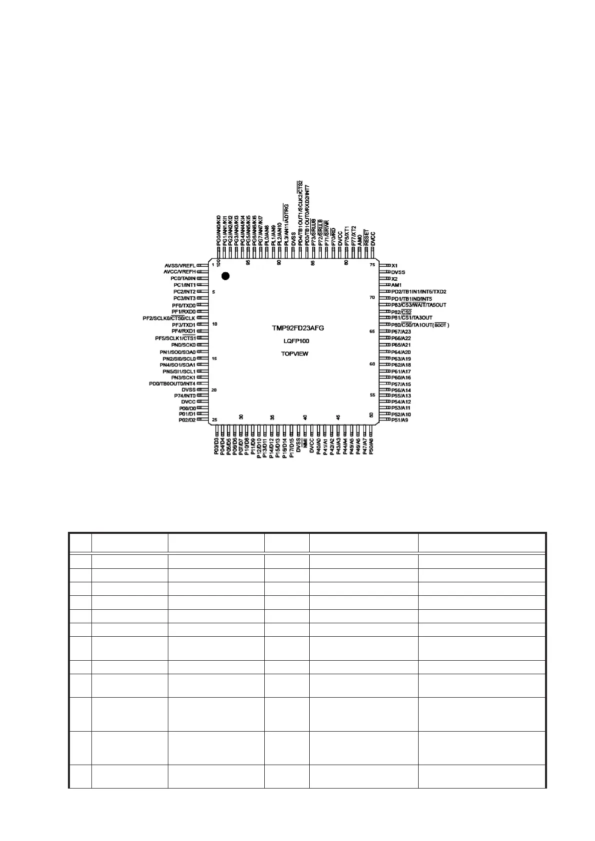
TMP92FD23AFG (IC11)
TMP92FD23AFG Terminal Functions
Pin
No
IC Terminal name Terminal name
I/O
Setting
Terminal function Remarks
1 AVSS/VREFL Power supply (GND) P Power supply (GND)
2 AVCC/VREFH Power supply (+3.3V) P Power supply (+3.3V)
3 PC0/TA0IN Non(PU) I Non(PU) Port only for input (Schmitt)
4 PC1/INT1 Non(PU) I POWER KEY Port only for input (Schmitt)
5 PC2/INT2 PLAY KEY I PLAY KEY Port only for input (Schmitt)
6 PC3/INT3 OP/CL KEY I OP/CL KEY Port only for input (Schmitt)
7 PF0/TXD0 FL_MDT O
FL tube communication line
(data)
(Schmitt I input)
8 PF1/RXD0 OPEN O Non (NC) (Schmitt I input)
9
PF2/SCLK0/CTS0/
CLK
FL_CLK O
FL tube communication line
(clock)
(Schmitt I input)
10 PF3/TXD1/HSSO [TXD] O
DENON BUS
[Communication lines for
writing]
(Schmitt I input)
11 PF4/RXD1/HSSI [RXD] I
DENON BUS
[Communication lines for
writing]
(Schmitt I input)
12
PF5/SCLK1/CTS1/
HSCLK
100KΩ/PD I (Schmitt I input)