EasyManua.ls Logo

Denon DCD-F109 Service Manual

Denon DCD-F109
84 pages
To Next Page IconTo Next Page
To Previous Page IconTo Previous Page
Page #81 background imageLoading...
Page #81 background image
81
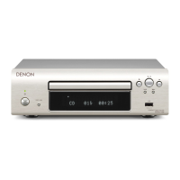
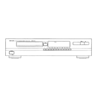
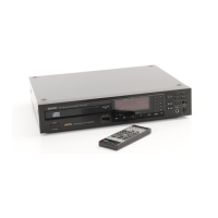
FRONT P.W.B. UNIT ASS'Y
Ref. No. Part No. Part Name Remarks Q'ty New
SEMICONDUCTORS GROUP
IC601 00D2630896909
IC,LINEAR OP,NJM2068MD-SOP8P
JP
J121206800030S
IC602 00D2623362903
IC,LOGIC-D/A CONVER,PCM1796DBR
JP
J042179600010S
IC603,604 00D2630896909
IC,LINEAR OP,NJM2068MD-SOP8P
JP
J121206800030S
IC609 963231101220S
IC,LINEAR-REGULATOR,KIA1117BPI33
E2
J126111733110S
*
IC610 00D2630810008
IC NJM7808FA J126780800030S
IC611 00D2622977946
IC,LINEAR-REGULATOR,BA33BC0FP J12603R300040S
IC612 00D2631251006
IC,LINEAR-REGULATOR,KIA7908PI J126790800060S
IC613 00D2630810008
IC NJM7808FA J126780800030S
IC614 963239007790M
IL1117_5.0 SOT-223 5.0V 1A LOW DROPOUT
JP
J126111750010S
IC615 00D2623203907
IC,LOGIC TC7SHU04F INVERTER 2V J040740400470S
Q500,501 00D2690192902
TR 2SC KRC102S (NB) J522010200210S
Q601 00D2730460905
TR KTC2875B(MB)
JP
J5222875B0010S
Q603 00D2730460905
TR KTC2875B(MB)
JP
J5222875B0010S
Q605 00D2690184907
TR KRA102S(PB)
JP
J520010200210S
Q606 00D2690192902
TR 2SC KRC102S (NB)
JP
J522010200210S
Q607 00D9630066606
KTC3875Y(ALY) 0.15W/SMT-REEL
JP
J5223875Y0210S
Q608 00D9630226705
TR KTC1027Y J5021027Y0020S
Q609 943214500020S
TR 2SC 2SC3052 J522305200050S
Q610 00D9630121606
TR KRC107S (NH)
JP
J522107S00210S
Q611,612 943214500020S
TR 2SC 2SC3052 J522305200050S
D500 963202500200S
D,ZENER CHIP PG05GBUSC K06605R010010S
D603,604 00D9630355401
D,SWITCHING KDS4148U
JP
K005041480030S
D608,609 00D9630328409
D,SWITCHING 1N4007 K000400700010S
D610,611 00D9630355401
D,SWITCHING KDS4148U K005041480030S
D612,613 00D9630328409
D,SWITCHING 1N4007 K000400700010S
D614 00D9630355401
D,SWITCHING KDS4148U K005041480030S
D615,616 963203500310S
D,RECTIFIER CHIP,M7 1000V 1A SMAJ K045007001020S
*
D617,618 00D9630328409
D,SWITCHING 1N4007 K000400700010S
D619,620 963203500310S
D,RECTIFIER CHIP,M7 1000V 1A SMAJ K045007001020S
*
D622,623 00D9630328409
D,SWITCHING 1N4007 K000400700010S
D625-629 00D9630328409
D,SWITCHING 1N4007 K000400700010S
D631 00D2760401905
D,SWITCHING 1SS133T K000013300520S
D632 00D9630355401
D,SWITCHING KDS4148U K005041480030S
D633-636 963203500310S
D,RECTIFIER CHIP,M7 1000V 1A SMAJ K045007001020S
*
D637,638 00D9630355401
D,SWITCHING KDS4148U K005041480030S
D639 00D9630328409
D,SWITCHING 1N4007 K000400700010S
D640 00D9630355401
D,SWITCHING KDS4148U K005041480030S
ZD601 00D2760761959
D,ZENER,MTZJ15B-0.5W/5MA-52MM
JP
K06015R044520S
*
ZD602 00D9630314206
D,ZENER MTZJ7.5B K06007R544520S
ZD603 00D9600095500
D,ZENER MTZJ5.1B K06005R144520S
ZD604 00D2760760905
D,ZENER MTZJ3.6B-0.5W/5MA K06003R644520S
ZD605 00D9600128105
D,ZENER MTZJ9.1B K06009R144520S
ZD606 00D9600096004
D,ZENER MTZJ33B K06033R044520S
LED500 963263100510S
LED WEJ3290W-R2H0-BA 3PI K500032451010S
RESISTORS GROUP
R652 nsp
R,FIXED,M.O. RSD-R0-1WJ-91
JP
N113135691020S
R686 00D9630337908
R,METAL 33-J,1W
FLAME
RETARDANT
C060033065050S
R694,695 nsp
R,METAL,330-J 1/4W-R,REEL C060033163050S
CAPACITORS GROUP
C500,501 nsp
C,CERAMIC 0.1UF-K/50V D011104577160S
C505-507 nsp
C,CERAMIC 0.1UF-K/50V D011104577160S
C509 nsp
C,CERAMIC 100PF-J/50V D010101167160S
C510 963134002720S
C,ELECT10UF-M/50V (Pb Free) D040100087080S
C511 nsp
C,CERAMIC 100PF-J/50V D010101167160S
C512,513 nsp
C,CERAMIC 0.1UF-K/50V D011104577160S
C514 nsp
C,CERAMIC 100PF-J/50V D010101167160S
C516-518 nsp
C,CERAMIC 0.1UF-K/50V D011104577160S
C519 nsp
C,CERAMIC 1000PF-K/50V D011102777160S
C520 nsp
C,CERAMIC 0.01UF-K/50V D010103777160S

Table of Contents

Other manuals for Denon DCD-F109

Questions and Answers:

Denon DCD-F109 Specifications

General IconGeneral
Audio formats supportedMP3, WMA
CD-RW playbackYes
CD changerNo
Device typeHiFi CD player
Product colorBlack
USB 2.0 ports quantity1
Weight and Dimensions IconWeight and Dimensions
Depth264 mm
Width250 mm
Height82 mm
Weight2800 g

Summary

Safety Precautions

Leakage Current Check

Procedure for checking leakage current before returning the set to the customer.

Cautions During Servicing and Inspection

General cautions and instructions for safe servicing and inspection.

Safety Check After Servicing

Checks to perform after servicing to ensure safety.

Important Safety Parts

Identifies and emphasizes the importance of using designated safety parts.

Warning and Laser Safety Instructions

Laser Safety

Warning about laser safety and the need for qualified personnel to service the unit.

Handling Semiconductors and Optical Unit

Grounding for Human Body

Procedure for grounding the human body to prevent static discharge.

Grounding for Workbench

Procedure for grounding the workbench to prevent static discharge.

Caution in Servicing

Handling and Replacement of Laser Pick-up

Determining Laser Pick-up Defectiveness

Method to test if the laser pick-up is defective using waveforms.

Assembly Cautions

Special Modes

CD Test Mode: Servo Operations

2.2. Servo Check

Detailed steps for performing servo checks.

CD Test Mode: Adjustment Values

2.7. Adjustment Value Display

How to display and check various adjustment values after auto adjustment.

CD Heat Run Modes

Error Display and Initialization

3.4. Error Display

Explanation of error codes and their meanings.

Firmware Upgrade Procedures

When Microprocessor is Replaced

Confirms settings after replacing the microprocessor or flash ROM.

1. How to Update by DISC

Instructions for updating firmware using a CD-R.

1.1. Procedure of Making CD-R

Steps to prepare a CD-R for firmware update.

1.2.2. USB µ-com Update

Steps to update the firmware for the USB µ-com.

Trouble Shooting Flowcharts

Flow Chart No. 1: Power Issues

Troubleshooting flowchart for power issues.

Flow Chart No. 2: +3.3V_D Output Issues

Troubleshooting flowchart for +3.3V_D output issues.

Flow Chart No. 3: Display Issues

Troubleshooting flowchart for fluorescent display not lighting up.

Flow Chart No. 4: Key Operation Issues

Troubleshooting flowchart for key operation not functioning.

Trouble Shooting Flowcharts (Continued)

Flow Chart No. 5: Remote Control Issues

Troubleshooting flowchart for remote control operation issues.

Flow Chart No. 6: Disc Tray Issues

Troubleshooting flowchart for disc tray opening/closing issues.

Flow Chart No. 7: Digital Output Issues

Troubleshooting flowchart for no sound from digital output.

Flow Chart No. 8: USB Play Issues

Troubleshooting flowchart for USB play issues.

Trouble Shooting Flowcharts (Final)

Flow Chart No. 9: CD Play Issues

Troubleshooting flowchart for CD play issues.

Measuring Methods and Waveforms

Waveforms

Disc Play RF Waveforms (Eye-Pattern)

RF waveforms during disc play for CD, CD-R.

Disc Detection Waveforms

Disc detection waveforms for CD, CD-R, CD-RW.

Block Diagram

Wiring Diagram

Printed Wiring Boards Overview

Printed Wiring Boards: Power and Front

Printed Wiring Boards: Power and DC-DC Converter

Schematic Diagrams (1/5): MCU Unit

Schematic Diagrams (2/5): Sub Power Unit

Schematic Diagrams (3/5): Audio Part

Schematic Diagrams (4/5): Power Part

Schematic Diagrams (4/5): Display Unit

Exploded View

Exploded View of CD Mechanism Unit

Parts List of Exploded View

Parts List of CD Mechanism Unit

Semiconductors

1. IC's (General List)

List and pinout of major ICs used in the unit.

IC Information: TMP92CD28AFG (IC15)

IC Information: TC94A92FG (IC17)

IC Information: IP4001 (IC14)CR

IC Information: PCM1796DBR (IC602)

Parts List of PCB Unit

Parts List of PCB Unit (Continued)

Parts List of PCB Unit (Final)

Front PWB Unit Assembly Parts

Front PWB Unit Assembly Parts (Continued)

Front PWB Unit Assembly Parts (Continued 2)

Front PWB Unit Assembly Parts (Final)

Related product manuals