


A
Anthony TaylorAug 18, 2025
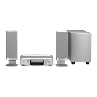
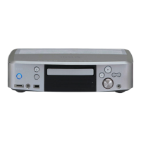
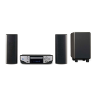
What to do if my Denon S-102 Home Theater System display is lit but there is no sound?
- Ddenise30Aug 18, 2025
If your Denon Home Theater System display is lit but no sound is produced, check the following: ensure the speaker cables are securely connected, verify that the selected input source matches the device you want to play, make sure the volume isn't set to the minimum, confirm that MUTING is off, and if using digital input, ensure digital signals are being input or select the correct input terminal.