EasyManua.ls Logo

Denon S-102 Service Manual

Denon S-102
125 pages
To Next Page IconTo Next Page
To Previous Page IconTo Previous Page
Page #99 background imageLoading...
Page #99 background image
99
S-102
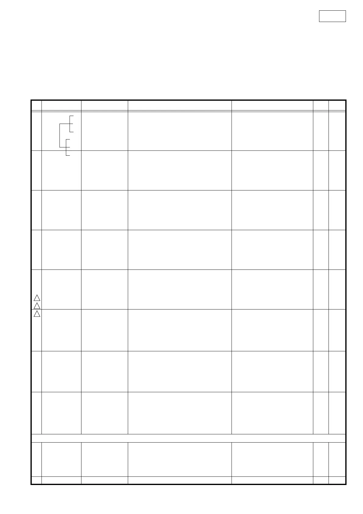
DSW-S102 PARTS LIST OF EXPLODED VIEW
*本表に"nsp" と記載されている部品は供給できません。
Parts for which "nsp" is indicated on this table cannot be supplied.
本表に"nsp" と記載されている基板 ASS’Y は供給できません。基板 ASS’Y の修理の際には基板部品表を確認のうえ、交換部品を発注してください。
P.W.B. ASS'Y for which "nsp" is indicated on this table cannot be supplied. When repairing the P.W.B. ASS'Y, check the board parts table and order replacement parts.
*本表に記載されている部品は、補修用部品のため製品に使用している部品とは一部、形状、寸法などが異なる場合があります。
The parts listed below are for maintenance only, might differ from the parts used in the unit in appearances or dimensions.
Note: The symbols in the column "Remarks" indicate the following destinations.
E3 : U.S.A. & Canada model E2 : Europe model JP : Japan model
Ref. No. Part No. Part Name Remarks Q'ty New
1 nsp D.AMP/SMPS P.W.B. UNIT ASS'Y(E2) for E2 1 *
1 nsp D.AMP/SMPS P.W.B. UNIT ASS'Y(E3) for E3 1 *
1 nsp D.AMP/SMPS P.W.B. UNIT ASS'Y(J) for JP 1 *
1-1 SMPA/AMP UNIT 1
1-2 I/F UNIT 1
1-4 AC I/F UNIT 1
2 00D 9H3 0001 728 DSWS102 CABINET ASSY 1 *
3 00D 105 1680 232 REAR PANEL 1*
4 00D 104 0354 003 FOOT(REAR) 2*
5 00D 461 1300 001 FELT 4*
6 nsp MAIN BRACKET 1 *
7 nsp P.W.B.HOLDER (H=12) 1
9 nsp HEAT SINK 1*
10 nsp SHIELD COVER 1 *
11 nsp CONNECTOR BRACKET 1 *
12 nsp TERMINAL COVER 1 *
13 00D 445 0084 009 CORD BUSH 3
14 nsp PEF SHEET(7x48) 2 *
15 nsp PEF SHEET(7x177) 2 *
16 nsp PEF SHEET(10x180) 2 *
17 nsp PEF SHEET(10x233) 2 *
18 00D 104 0353 004 FOOT(FRONT) 2 *
I19 00D 206 2244 006 AC CORD E2withCON(V) for E2 1
I19 00D 206 2245 005 AC CORD E3withCON(V) for E3 1
I19 00D 206 2248 002 AC CORD JwithCON (V) for JP 1
20 00D 445 0131 004 CORD BUSH(SR-5K4) 1
★ 21
00D 461 1316 008 PEF SHEET(10x10) 1 *
★ 22
nsp SPACER(CPVS-0.5F) 2 *
★ 23
00D 342 0040 003 FERRITE CRAMP081610N CX041 1
24 nsp PWB PAD 1*
★ 25
nsp PEF SHEET(10x15) 5 *
★ 26
nsp PEF SHEET(30x120) 4 *
27 nsp CABINET PAD(70X15) 1 *
28 nsp CABINET PAD(70X15) 1 *
★ 29
nsp RATING SHEET(E2) 1 *
★ 29
nsp RATING SHEET(E3) 1 *
★ 29
nsp RATING SHEET(J) 1 *
★ 30
nsp DATE LABEL 1
wires
★ 51
00D 203 6644 001 4P VH-VH CON.CORD CX04-1CY042 1 *
★ 52
00D 204 3021 002 8P PH-PH CON.CORD CX081-CY082 1 *
★ 53
00D 203 2447 008 2P VA-VA CON.CORD CX021-CY021 1 *
★ 54
00D 204 6821 018 15P PH-PH CON.CORD CX151-CY152 1 *
!
!
!

Other manuals for Denon S-102

Questions and Answers:

Denon S-102 Specifications

General IconGeneral
Audio decodersDolby Digital, DTS
RMS rated power70 W
Audio output channels2.1 channels
Audio formats supportedMP3, WMA
Tweeter diameter25 mm
Weight3800 g
Set width380 mm
Dimensions (WxDxH)380 x 93 x 293 mm
Mid-range driver diameter80 mm
Radio Data System (RDS)Yes
Optical disc player typeDVD player
Power consumption (standby)0.3 W
Power consumption (typical)51 W
Weight and Dimensions IconWeight and Dimensions
Subwoofer weight10500 g
Subwoofer dimensions (WxDxH)408 x 378 x 212 mm
Front speaker dimensions (WxDxH)76 x 258 x 103 mm

Summary

Safety Precautions

General Cautions

Key safety points for servicing: electric shock, disassembly, parts usage, and wiring arrangement.

Leakage Current Check

Procedure to check leakage current before returning the unit to the customer.

Laser Radiation Warning

Caution regarding laser beam exposure during servicing.

Product Dimensions

ADV-S102 Dimensions

Dimensional drawings and measurements for the ADV-S102 unit.

DSW-S102 Dimensions

Dimensional drawings and measurements for the DSW-S102 unit.

SC-S102 Dimensions

Dimensional drawings and measurements for the SC-S102 unit.

Wire Arrangement Procedures

ADV-S102 Wire Arrangement

Instructions for neatly arranging wires after servicing the ADV-S102 unit.

DSW-S102 Wire Arrangement

Instructions for neatly arranging wires after servicing the DSW-S102 unit.

Disassembly Instructions

ADV-S102 Disassembly

Step-by-step guide for disassembling the ADV-S102 unit.

Loader Panel Removal

Procedure to detach the loader panel from the ADV-S102.

Side Panel Removal

Procedure to detach the side panel from the ADV-S102.

Top Cover Removal

Procedure to detach the top cover from the ADV-S102.

DVD Mecha. Unit Removal

Procedure to detach the DVD mechanism unit from the ADV-S102.

Front Panel Assembly Removal

Procedure to detach the front panel assembly from the ADV-S102.

Back Panel Assembly Removal

Procedure to detach the back panel assembly from the ADV-S102.

DSW-S102 Disassembly

Step-by-step guide for disassembling the DSW-S102 unit.

Rear Panel Removal

Procedure to detach the rear panel from the DSW-S102.

Shield Cover Removal

Procedure to detach the shield cover from the DSW-S102.

Optical Pickup Diagnostics and Traverse Unit Replacement

Iop Checked Method

Method for checking laser drive current (Iop) for diagnostics.

Laser Current Checks (DVD/CD)

Procedure to check DVD and CD laser drive current (Iop).

Laser Pick-Up Handling Notes

Important precautions for handling the laser pick-up unit.

Laser Pick-Up Replacement (Traverse Unit)

Procedure for replacing the traverse unit (laser pick-up).

Laser Current Value Adjustments

Procedure to rewrite default laser current and reset accumulated time.

Traverse Unit Replacement Procedure

Guide Clamp Bracket Disassembly

Procedure to disassemble the guide clamp bracket.

Tray Disassembly

Procedure to disassemble the tray mechanism.

Traverse Unit Disassembly

Procedure to disassemble the traverse unit itself.

Service and Setting Modes

Aging Mode Operations

Procedures for operating the unit in aging mode.

Aging Mode Preparation

Required equipment and unit settings for aging mode.

Aging Mode Procedure

Step-by-step guide for performing the aging mode operation.

Initial Setting Mode

Procedures for initializing unit settings like functions and mechanisms.

Initial Setting Mode Preparation

Requirements for entering the initial setting mode.

Initial Setting Mode Procedure

Steps to perform system and DVD initialization.

µcom Firm Check Mode

Procedure to display firmware version and related information.

Firm Check Mode Preparation

Requirements for entering the firm check mode.

Firm Check Mode Procedure

Steps to display firmware version and system information.

Test Mode Operations

Guide to entering and using various test modes for diagnostics.

Entering and Selecting Test Modes

How to access and select desired test modes.

Setting and Changing Test Modes

How to confirm and navigate between test modes.

Trace Mode Execution (Error Rate Display)

How to perform trace mode to display error rates.

Other Test Mode Operations

Other operations available within the test mode.

Troubleshooting Specific Issues

ADV-S102 Troubleshooting

Specific troubleshooting steps for the ADV-S102 unit.

FL Tube Not Lighting

Troubleshooting steps when the front panel display tube is not lighting.

No Sound/Noise Generation (CD/DVD Play)

Troubleshooting steps for no sound or noise during CD/DVD playback.

DVD Playback Issues

Troubleshooting for specific DVD playback problems.

Analog Input Issues (AUX/Y/C)

Troubleshooting for issues related to AUX IN and Y/C input signals.

DSW-S102 Troubleshooting

Specific troubleshooting steps for the DSW-S102 unit.

Amplifier Section Issues

Troubleshooting steps for the DSW-S102 amplifier section.

Waveform Analysis

Guide to analyzing waveforms for the DSW-S102 unit.

Power Supply Issues

Troubleshooting steps for power supply problems in the DSW-S102.

Electrical Adjustments

Video Signal Adjustment

Steps for adjusting video signal levels using an oscilloscope.

S-VIDEO Out Signal Adjustment

Procedure to adjust S-VIDEO output signal levels.

Component Out Signal Adjustment

Procedure to adjust component video output signal levels.

Block Diagrams

ADV-S102 Block Diagram

Functional block diagram of the ADV-S102 unit.

DSW-S102 Block Diagram

Functional block diagram of the DSW-S102 unit.

Semiconductor Information

IC Pinout and Descriptions

Detailed pin configurations and descriptions for key ICs used in the unit.

Printed Wiring Board Layouts

Diagrams showing the component and foil sides of the main PWB units.

Parts Lists

PWB Parts List

List of semiconductor, resistor, and capacitor parts for PWB units.

Exploded View Parts List

Parts list corresponding to the exploded view of PWB units.

Packing & Accessories Parts List

List of packing materials and accessories included with the unit.

Wiring Diagrams

ADV-S102 Wiring Diagram

Circuit diagram showing the connections for the ADV-S102 unit.

DSW-S102 Wiring Diagram

Circuit diagram showing the connections for the DSW-S102 unit.

Measuring Methods and Waveforms

Waveforms IU-3807 FEP Unit

Example waveforms captured from the IU-3807 FEP Unit for analysis.

Schematic Diagrams (1/17) - 1U-3807 FEP Unit

Schematic Diagrams (2/17) - 1U-3836-1 Main Unit (B/E Block)

Schematic Diagrams (3/17) - 1U-3836-1 Main Unit (I/F Block)

Schematic Diagrams (4/17) - 1U-3836-1 Main Unit (uCOM Block)

Schematic Diagrams (5/17) - 1U-3836-1 Main Unit (Audio DSP Block)

Schematic Diagrams (6/17) - 1U-3836-1 Main Unit (Codec/Dir Block)

Schematic Diagrams (7/17) - 1U-3836-1 Main Unit (Function/Volume Block)

Schematic Diagrams (8/17) - 1U-3836-1 Main Unit (IP/HDMI/PLD Block)

Schematic Diagrams (9/17) - 1U-3836-1 Main Unit (Video Encoder/In-Out Block)

Schematic Diagrams (10/17) - 1U-3831-4 Local Power Unit

Schematic Diagrams (11/17) - 1U-3831 Unit Group

1U-3831-1 Display Center Unit Schematic

Circuit schematic for the Display Center Unit.

1U-3831-2 Display Right Unit Schematic

Circuit schematic for the Display Right Unit.

1U-3831-3 Display Left Unit Schematic

Circuit schematic for the Display Left Unit.

1U-3831-5 HP Out Unit Schematic

Circuit schematic for the HP Out Unit.

1U-3831-6 Aux In Unit Schematic

Circuit schematic for the Aux In Unit.

1U-3831-7 IF-1 Unit Schematic

Circuit schematic for the IF-1 Unit.

Schematic Diagrams (12/17) - 1U-3811 Unit Group

1U-3811-3 I/F Unit Schematic

Circuit schematic for the 1U-3811-3 I/F Unit.

1U-3811-4 AC I/F Unit Schematic

Circuit schematic for the 1U-3811-4 AC I/F Unit.

Schematic Diagrams (13/17) - 1U-3811-1 D.AMP/SMPS Unit (1/3)

Schematic Diagrams (14/17) - 1U-3811-1 D.AMP/SMPS Unit (2/3)

Schematic Diagrams (15/17) - 1U-3811-1 D.AMP/SMPS Unit (3/3) (for E2 model)

Schematic Diagrams (16/17) - 1U-3811-1 D.AMP/SMPS Unit (3/3) (for E3 model)

Schematic Diagrams (17/17) - 1U-3811-1 D.AMP/SMPS Unit (3/3) (for JP model)

Related product manuals